2-16
X9SKV Motherboard Series User's Manual
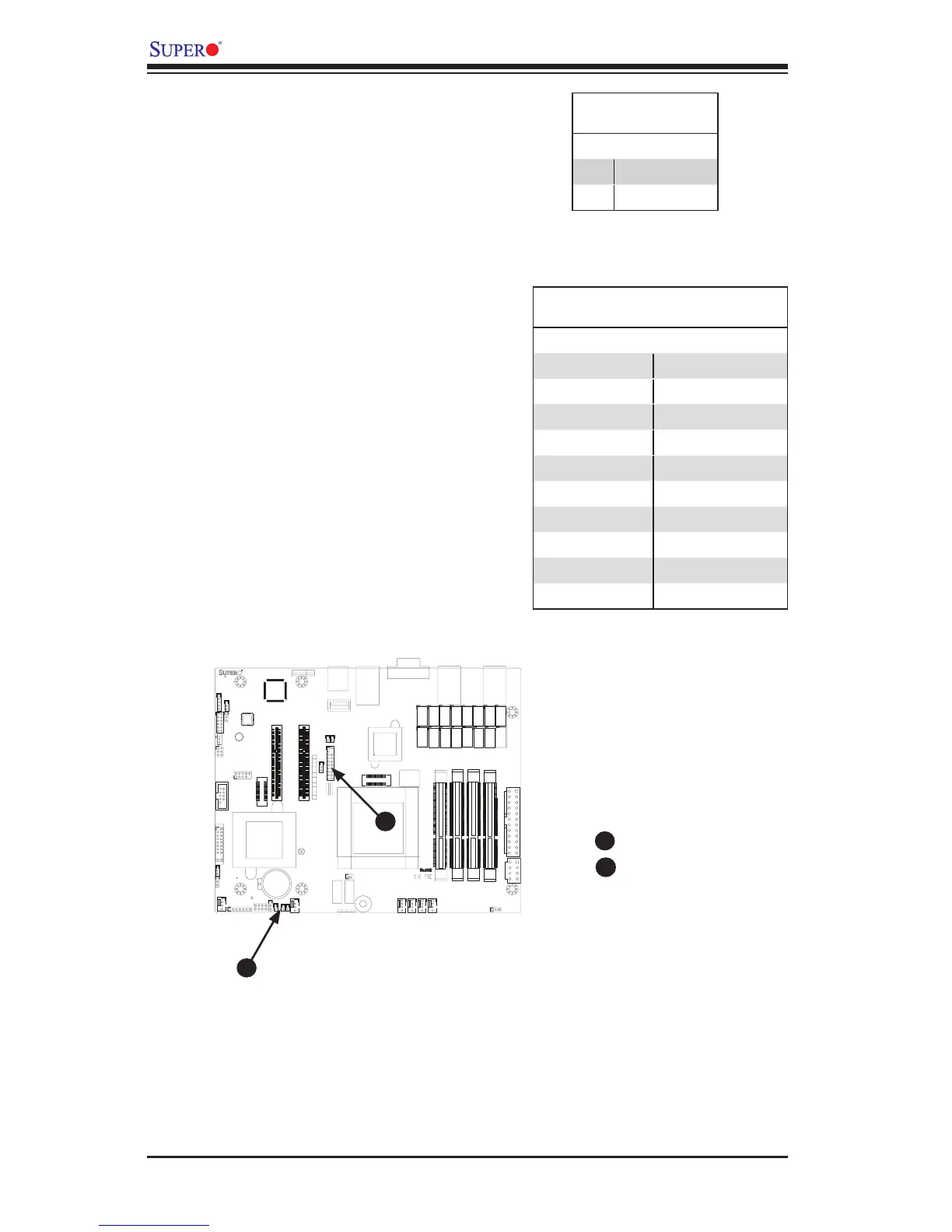
Chassis Intrusion (JL1)
A Chassis Intrusion header is located
at JL1 on the motherboard. Attach the
appropriate cable from the chassis to
inform you of a chassis intrusion when
the chassis is opened.
Chassis Intrusion
Pin Denitions (JL1)
Pin# Denition
1 Intrusion Input
2 Ground
1
1
1
+
1
DESIGNED IN USA
+
3
1
19
20
1
1
1
1
1
4
1
4
1
4
1
4
JSTBY1
JPME2
JPF2
JVR1
JPF1
JMCURST1
JPSLOT1
JPW2
JGPIO1
T1
T10
T11
T12
T13
T14
T15
T16
T2
T3
T4
T5
T6
T7
T8
T9
JDEBUG1
BT1
JCOM2
JP1
SP1
JF2
JUSB2
JBT1
JSD1
JTPM1
LED5
JD1
JOH1
JL1
JWOR1
JI2C1
JI2C2
JITP2
JITP1
JPW1
FAN6
FAN5
FAN4
FAN3
FAN1/CPU1
FAN2
I-SATA1
I-SATA0
JF1
JPCIE2
JPCIE1
JWD1
BUZZER
XDP-PXH
XDP-CPU
2-3:ME MANUFACTURING MODE
1-2:NORMAL
JTAG OF MCU
COM2 TO MCU
2-4&3-5
4-7:SPEAKER
1-3:PWR LED
UARTB TO MCU
UARTB TO COM2
1-2&5-6
1-3&4-6
COM2
JD1:
JDEBUG1: MCU DEBUG PORT
USB2/3
BATTERY
SLOT6 PCI-E 2.0 X 8
:OH LED
CMOS CLEAR
JF2:
X
SLOT7 PCI-E 2.0 X 8
X
ON
PWR
FR/NMI
RST
OH/FF
PP1
NIC6
PP0
NIC5
JF1
LED
HDD
LED
PWR
NMI
NIC4
JSD1:
USB0/1
2-3:SLOT6
1-2:SLOT7
JPSLOT1:PCI-E SLOT SELECT
JTPM1:TPM/PORT80
OFF:DISABLE
ON:ENABLE
WAKE ON RING
JWOR1:
NIC3
SATA DOM POWER
JI2C1/JI2C2
NIC1NIC2
LAN5/LAN6
2-3:NORMAL
1-2:BYPASS LAN LED
JL1:
JPF1:JPF2:
1-2:FR/NMI
2-3:NORMAL
CHASSIS INTRUSION
CPU
COM1
DIMMA1
UNB ECC DDR3 SODIMM REQUIRED
DIMMA2
ALWAYS POPULATE DIMMx2 FIRST
DIMMB1
DIMMB2
LAN3/LAN4
LAN1/LAN2
USB4
Chassis Intrusion
TPM Header
A
B
A
B
TPM Header (JTPM1)
This header is used to connect a Trusted
Platform Module (TPM), available from
a third-party vendor. A TPM is a secu-
rity device that allows encryption and
authentication of hard drives. It enables
the motherboard to deny access if the
TPM associated with the hard drive is not
installed in the system. See the table on
the right for pin denitions.
Trusted Platform Module Header
Pin Denitions
Pin # Denition Pin # Denition
1 LCLK 2 GND
3 LFRAME 4 No Pin
5 LRESET 6 VCC5
7 LAD3 8 LAD2
9 VCC3 10 LAD1
11 LAD0 12 GND
13 RSV0 14 RSV1
15 3VSB 16 SERIRQ
17 GND 18 CLKRUN
19 3VSB 20 RSV2
 Loading...