Chapter 2: Installation
2-13
Power Button
1
LAN5 (Link/Activity) LED
Reset Button
2
HDD LED
FP Power LED
3.3V SB
3.3V
3.3V SB
OH/Fan Fail LED
Ground
Ground
1920
Key
Ground
NMI
Key
3.3V SB
LAN6 (Link/Activity) LED
Power Fail
3.3V
3.3V
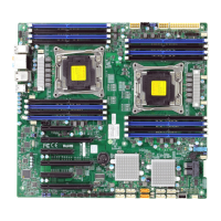
Power Button
The Power Button connection is located
on pins 1 and 2 of JF1. Momentarily
contacting both pins will power on/off the
system. To turn off the power when set
to suspend mode, press the button for
at least 4 seconds. Refer to the table on
the right for pin denitions.
Power Button
Pin Denitions (JF1)
Pin# Denition
1 Signal
2 Ground
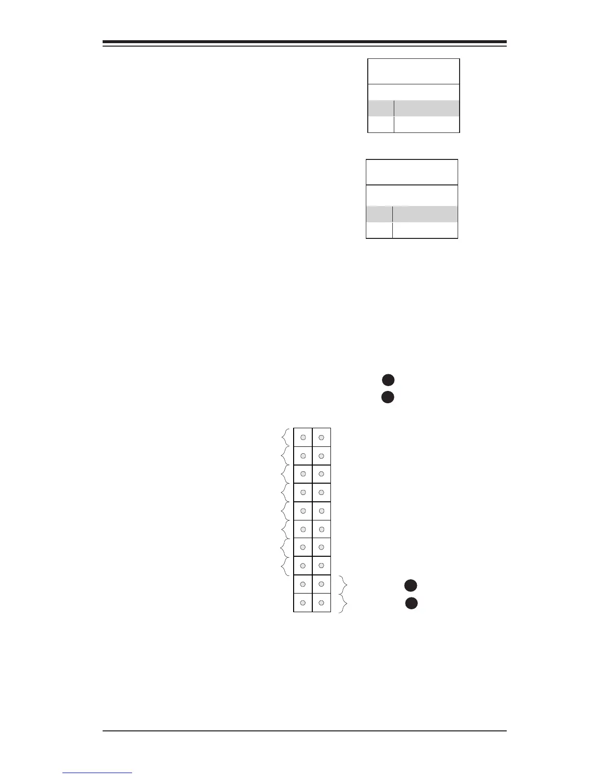
Reset Button
The Reset Button connection is located
on pins 3 and 4 of JF1. Attach it to a
hardware reset switch on the computer
case. Refer to the table on the right for
pin denitions.
Reset Button
Pin Denitions (JF1)
Pin# Denition
3 Reset
4 Ground
Reset Button
PWR Button
A
B
JF1 Header Pins
A
B
 Loading...