2-12
X9SPV Motherboard Series User's Manual
1
JWD1
UID
VGA
JWP1:WRITE PROTECT
PWR I2C
U60
I-SATA0I-SATA1
JVGA1
JIPMB1
T-SGPIO2T-SGPIO1
JSD1
I-SATA5
I-SATA2
I-SATA4
I-SATA3
J1
J3
F6
JCOM2
J20USB1
SP1
LED2
LED1
LED3
U21
U7
U10
U22
U6
JDIMM1
JDIMM2
JCOM1
FAN2FA N3
FAN1
FAN4
U26
JPW1
JPI2C1
JPK1
U3
JTPM1
JLAN1JLAN2
MH7
MH6
MH2
MH4
JD1
JF1
JP1
JPUSB1
JPB1
JWP1
JL1 JOH1
MH4
U57
X9SPV-F
JTPM1:TPM/PORT80
DOM POWER
P1-DIMMB1
USB8/9
IPMI
JSD1:SATA
COM2
USB6/7
LAN2/4
LAN1/3
P1-DIMMA1
COM1
USB4/5
KB/MOUSE
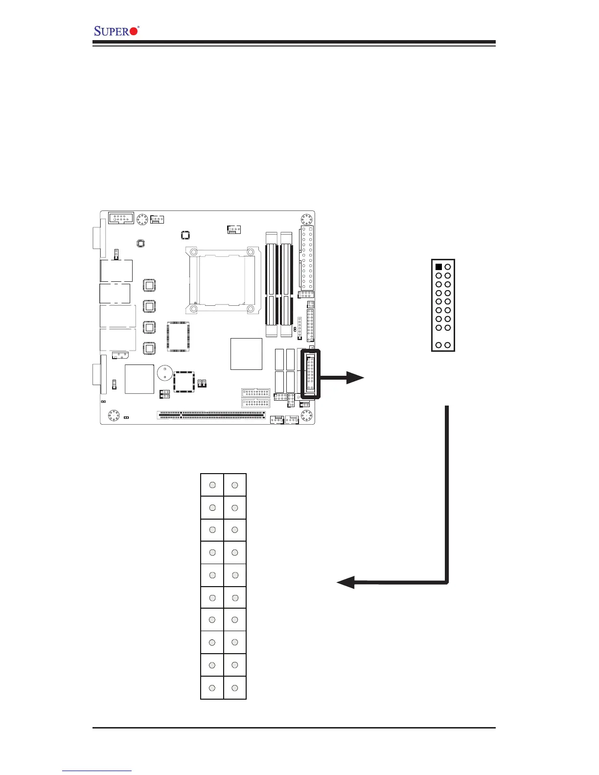
Front Control Panel
JF1 contains header pins for various buttons and indicators that are normally lo-
cated on a control panel at the front of the chassis. These connectors are designed
specically for use with Supermicro server chassis. See the gure below for the
descriptions of the various control panel buttons and LED indicators. Refer to the
following section for descriptions and pin denitions.
JF1 Header Pins
Power Button
OH/Fan Fail LED
 Loading...


