HDD LED
Power LED
Vcc
Vcc
Vcc
Vcc
Ground
Ground
19 20
X
Ground
NMI
X
Vcc
NIC2 LED
X
X
OH/Fan Fail LED
Power Fail LED
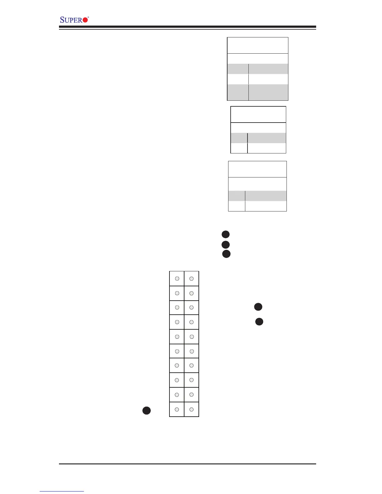
NMI Button
Overheat (OH)/Fan Fail LED
Connect an LED Cable to the OH/Fan
Fail connection on pins 7 and 8 of JF1
to provide advanced warnings of chassis
overheat or fan failure. Refer to the table
on the right for pin denitions.
OH/Fan Fail Indicator
Status
State Denition
Off Normal
On Overheat
Flash-
ing
Fan Fail
A
B
JF1 Header Pins
A
B
C
C
NMI Button
The non-maskable interrupt button
header is located on pins 19 and 20 of
JF1. Refer to the table on the right for
pin denitions.
NMI Button
Pin Denitions (JF1)
Pin# Denition
1 Signal
2 Ground
Power Fail LED
The Power Fail LED connection is lo-
cated on pins 5 and 6 of JF1. Refer to the
table on the right for pin denitions.
Power Fail LED
Pin Denitions (JF1)
Pin# Denition
5 Vcc
6 Ground
 Loading...


