JTPM1:TPM/PORT80
DOM POWER
P1-DIMMB1
USB8/9
IPMI
JSD1:SATA
COM2
USB6/7
LAN2/4
LAN1/3
P1-DIMMA1
COM1
USB4/5
KB/MOUSE
SATA DOM Power
SMB I2C Connector
IPMI SMB
A
B
A
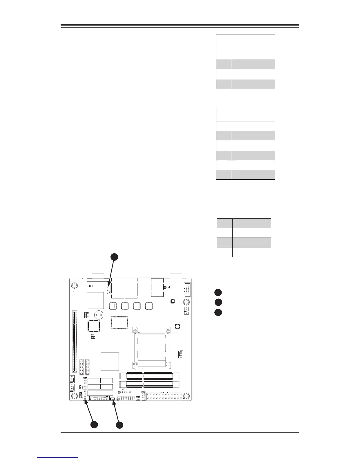
SATA DOM Power (JSD1)
The SATA DOM Power on JSD1 is used
to supply power to SATA Disk-on-Module
(DOM) solid-state storage devices.
B
Power SMB I
2
C Connector (JPI2C1)
Power System Management Bus (I
2
C)
connector enables monitoring the status
of the power supply, fan and system
temperature. See the table on the right
for pin denitions.
PWR Supply I
2
C
Pin Denitions
Pin# Denition
1 Clock
2 Data
3 PWR Fail
4 Ground
5 +3.3V
SATA DOM Power
Pin Denitions
Pin# Denition
1 +5V
2 Ground
3 Ground
System Management Bus (JIPMB1)
A System Management Bus header for the
IPMI slot is located at IPMB. Connect the
appropriate cable here to use the IPMB I2C
connection on your system.
System Management
Bus
Pin# Denition
1 Clock
2 Ground
3 Data
4 No Connection

 Loading...


