Chapter 2: Installation
2-17
1
JWD1
UID
VGA
JWP1:WRITE PROTECT
PWR I2C
U60
I-SATA0I-SATA1
JVGA1
JIPMB1
T-SGPIO2T-SGPIO1
JSD1
I-SATA5
I-SATA2
I-SATA4
I-SATA3
J1
J3
F6
JCOM2
J20USB1
SP1
LED2
LED1
LED3
U21
U7
U10
U22
U6
JDIMM1
JDIMM2
JCOM1
FAN2FAN3
FAN1
FAN4
U26
JPW1
JPI2C1
JPK1
U3
JTPM1
JLAN1JLAN2
MH7
MH6
MH2
MH4
JD1
JF1
JP1
JPUSB1
JPB1
JWP1
JL1 JOH1
MH4
U57
X9SPV-F
JTPM1:TPM/PORT80
DOM POWER
P1-DIMMB1
USB8/9
IPMI
JSD1:SATA
COM2
USB6/7
LAN2/4
LAN1/3
P1-DIMMA1
COM1
USB4/5
KB/MOUSE
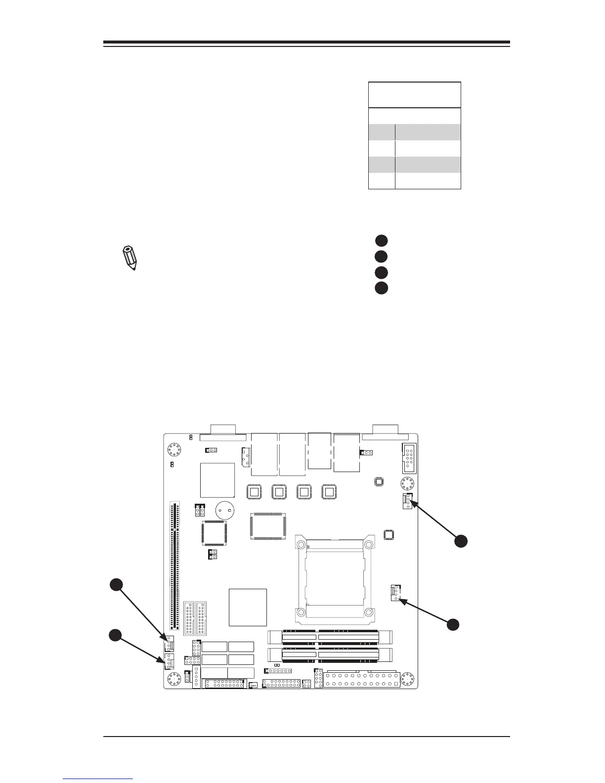
Fan Header
Pin Denitions
Pin# Denition
1 Ground
2 +12V
3 Tachometer
4 PWM_Control
Fan Headers
The X9SPV Motherboard Series has
three fan headers (Fan1~Fan3). These
fans are 4-pin fan headers. Although
Pins 1~3 of the fan headers are back-
ward compatible with the traditional
3-pin fans, please 4-pin fans on the
motherboard to enable the motherboard
to control fan speed through the BIOS.
Refer to the table on the right for pin
denitions.
Note: The speeds of 4-pin (PWM)
fans are controlled by Thermal
Management via BIOS Hardware
Monitoring in the Advanced Setting.
(The default setting is Disabled.)
A
B
Fan1
Fan2
Fan3
Fan4
A
B
C
C
D
D

 Loading...


