iv
LIST OF FIGURES
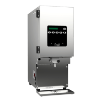
Figure 1: Main exterior components of the AC110-PC ......................................................................................................... 1
Figure 2: Main interior components of the AC320-FP ........................................................................................................... 1
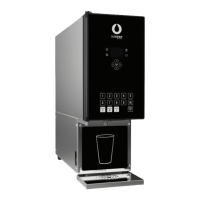
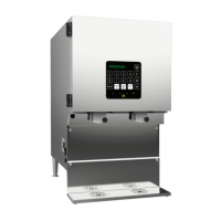
Figure 3: Main exterior components AC230-SS with self-serve dispense handles and illuminated display ............ 2
Figure 4: Main exterior components AC330-SS with low touch cup levers and illuminated display ......................... 2
Figure 5: Illuminated door display ............................................................................................................................................ 6
Figure 6: Open door display panel .......................................................................................................................................... 7
Figure 7: Remove graphic from door display panel ............................................................................................................ 7
Figure 8: Product case ................................................................................................................................................................. 8
Figure 9: Dairy bag fitment secured on product case floor ................................................................................................ 9
Figure 10: Open valve door ....................................................................................................................................................... 9
Figure 11: Correct tube placement ........................................................................................................................................... 9
Figure 12: Cutting the tube ......................................................................................................................................................... 9
Figure 13: Bag-in-box ................................................................................................................................................................. 10
Figure 14: Open valve door ..................................................................................................................................................... 10
Figure 15: Correct tube placement ......................................................................................................................................... 10
Figure 16: Cutting the tube ....................................................................................................................................................... 11
Figure 17: Refillable tank .......................................................................................................................................................... 11
Figure 18: Flip lid on top of dispenser ................................................................................................................................... 12
Figure 19: Open valve door ..................................................................................................................................................... 12
Figure 20: Correct tube placement ......................................................................................................................................... 12
Figure 21: Fill-in-Place model (AC330-FP) .............................................................................................................................. 13
Figure 22: Open valve door ..................................................................................................................................................... 13
Figure 23: Correct tube placement ......................................................................................................................................... 14
Figure 24: Cutting the tube ....................................................................................................................................................... 14
Figure 25: Open valve door ..................................................................................................................................................... 14
Figure 26: Correct tube placement ......................................................................................................................................... 15
Figure 27: Properly cut tube ..................................................................................................................................................... 15
Figure 28: Button panel for the AC320 .................................................................................................................................. 16
Figure 29: Button panel for the AC110 .................................................................................................................................. 21
Figure 30: Side console ............................................................................................................................................................. 25
Figure 31: Removing metal valve insert ................................................................................................................................ 30
Figure 32: Removing valve body ............................................................................................................................................. 30
Figure 33: Remove the reed switch and attached metal valve insert ............................................................................ 31
Figure 34: Remove spring retainer ......................................................................................................................................... 31
Figure 35: Valve spring cup ...................................................................................................................................................... 31
Figure 36: Install the plunger and spring into the solenoid .............................................................................................. 32
Figure 37: Insert plunger tip through dispense handle or cup lever plate ................................................................... 33
Figure 38: Self-serve dispense handle and valve assembly ............................................................................................. 33
Figure 39: Condenser fins ......................................................................................................................................................... 34
Figure 40: Product identification label ................................................................................................................................... 38
 Loading...