8 Installation
Pin assignment – M12 connector
Output Type Connector Pin 1 Pin 2 Pin 3 Pin 4 Pin 5
Modbus RTU A SDI -VB +VB N/A N/A
B GND -VB +VB +D -D
Pulse and analog A SDI -VB +VB N/A N/A
B N/A SW SW +I -I
M-Bus
A SDI -VB +VB N/A N/A
B N/A -VB +VB M-Bus M-Bus
Modbus TCP A SDI -VB +VB
N/A N/A
B See section 8.7.2 on the next page .
Wire color / brown white blue black grey
Legend for pin assignment
GND: Ground for Modbus RTU
SDI: Digital signal (internal use)
-VB: Negative supply voltage
+VB: Positive supply voltage
+l: Positive 4 … 20 mA signal
-I: Negative 4 ... 20 mA signal
SW: Isolated pulse switch input/output
D+: Modbus RTU data +
D-: Modbus RTU data -
M-Bus: M-Bus data
N/A: Not applicable
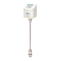
ATTENTION!
Do not screw the M12 connector using force.
Otherwise it might damage the connection pins.
S430 29