8 Installation
8.7.2 Ethernet connection
The device can be powered in the following ways:
• Using connector A
• Using the PoE function, which is integrated into the Ethernet
connection on connector B.
To power the unit via PoE, a switch that supports PoE is needed.
PoE comes into two different standards:
• Type A: PoE switch powers the device via Pair 2 (Pin 1 and Pin 2)
and Pair 3 (Pin 3 and Pin 6)
• Type B: PoE switch powers the device via Pair 1 (Pin 4 and Pin 5)
and Pair4 (Pin 7 and Pin 8)
This device supports both types.
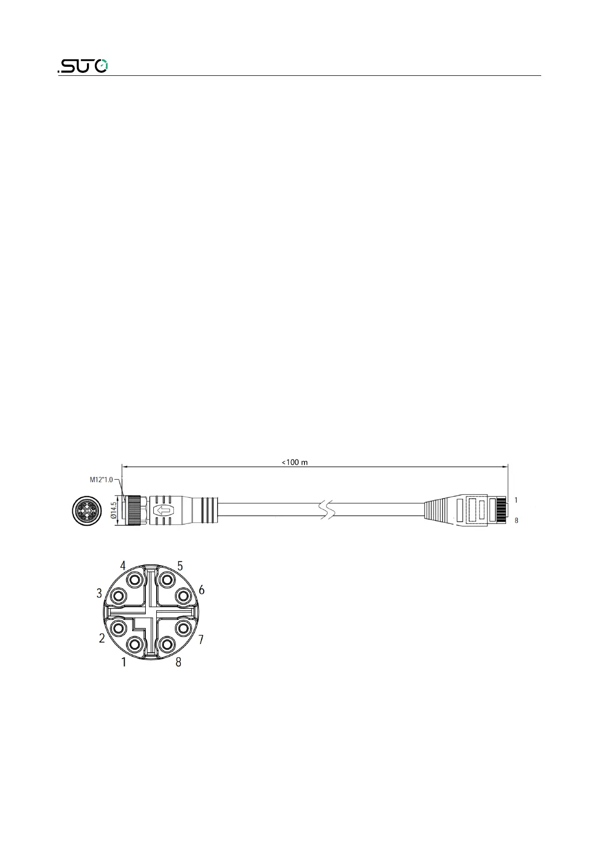
Connection cable – M12 X-coded to RJ45
When Modbus TCP is chosen as the sensor output, a 5 m 8-pore cable is
supplied in the delivery package, which has the M12 and RJ45 plugs on
both ends. RJ45 is used to connect the device to a PoE switch.
Pin front view of M12 connector, female
30 S430