8 Installation
8.7 Performing the electrical connection
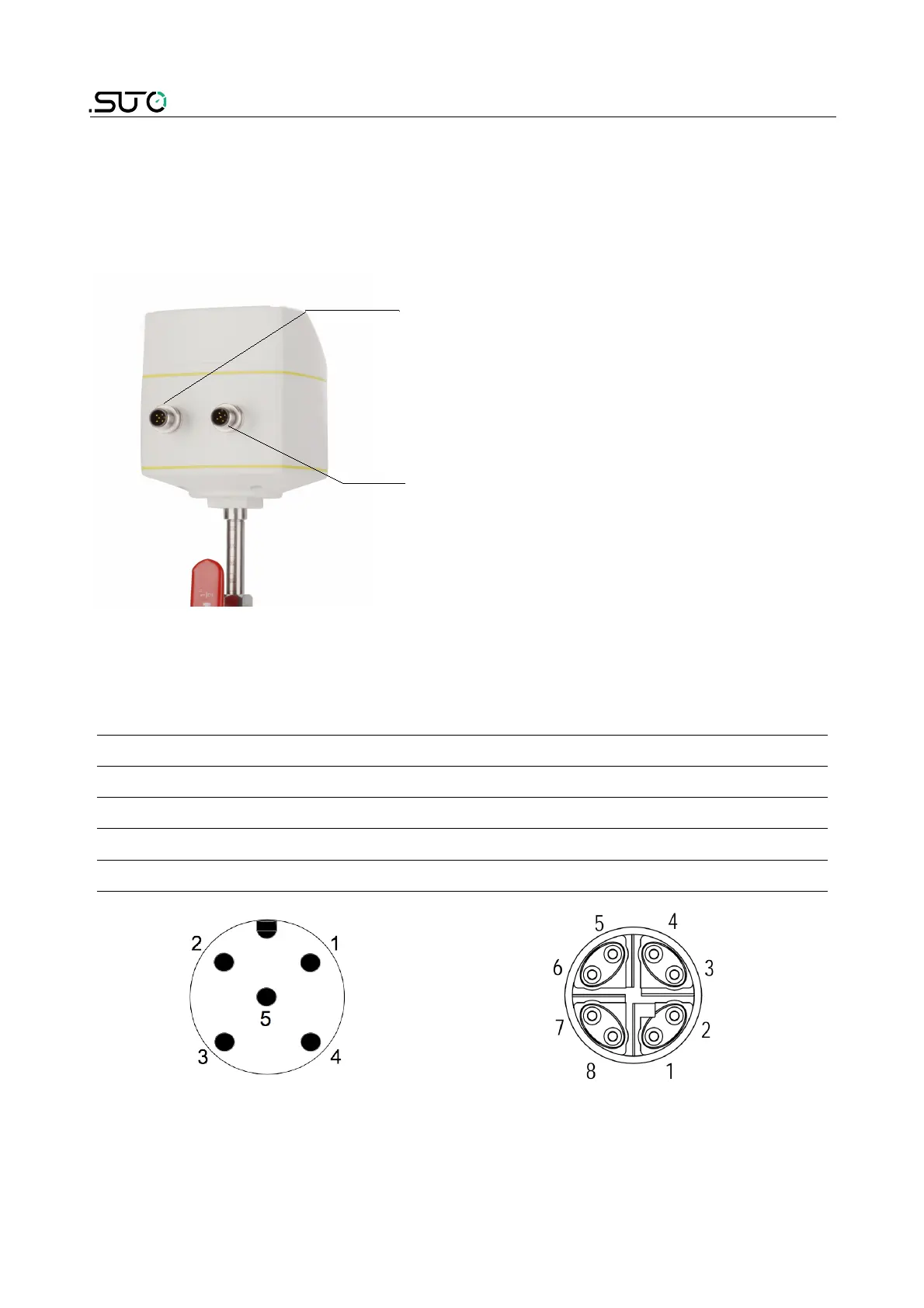
The flow sensor comes with external connectors "A" and "B" through
which the sensor is connected with external control devices such as
PLC.
Connector A
Connector B
8.7.1 M12 connectors
The following table lists the type of the M12 connector based on the
output option.
P/N Output option Connector type
A1061 Modbus RTU A = M12 (5-pin); B = M12 5-pin
A1062 Pulse and analog A = M12 (5-pin); B = M12 5-pin
A1063 M-Bus A = M12 (5-pin); B = M12 5-pin
A1064 Modbus TCP A = M12 (5-pin); B = M12 8-pin X-coded
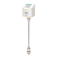
General connection pins, male
(View onto the sensor connector)
Ethernet connection pins, male
(View onto the sensor connector)
28 S430