Bit 6
Add 1 time doo-lock break when
the inspction to normal
Bit 7 No error display on the small keypad
Bit 8
Canccel the door-open order
immdiate after the door-open limit
Bit 9
Elevator stop when the feedback is
abnormal
Cancel the door-open order 1 s
after the door-open limit
Bit 10 Reserved Bit 11 Reserved
Bit 12 Reserved Bit 13 Reserved
Bit 14 Reserved Bit 15 Reserved
F5-34
F5-35
Terminal state display Default Min. Unit
Setting Range
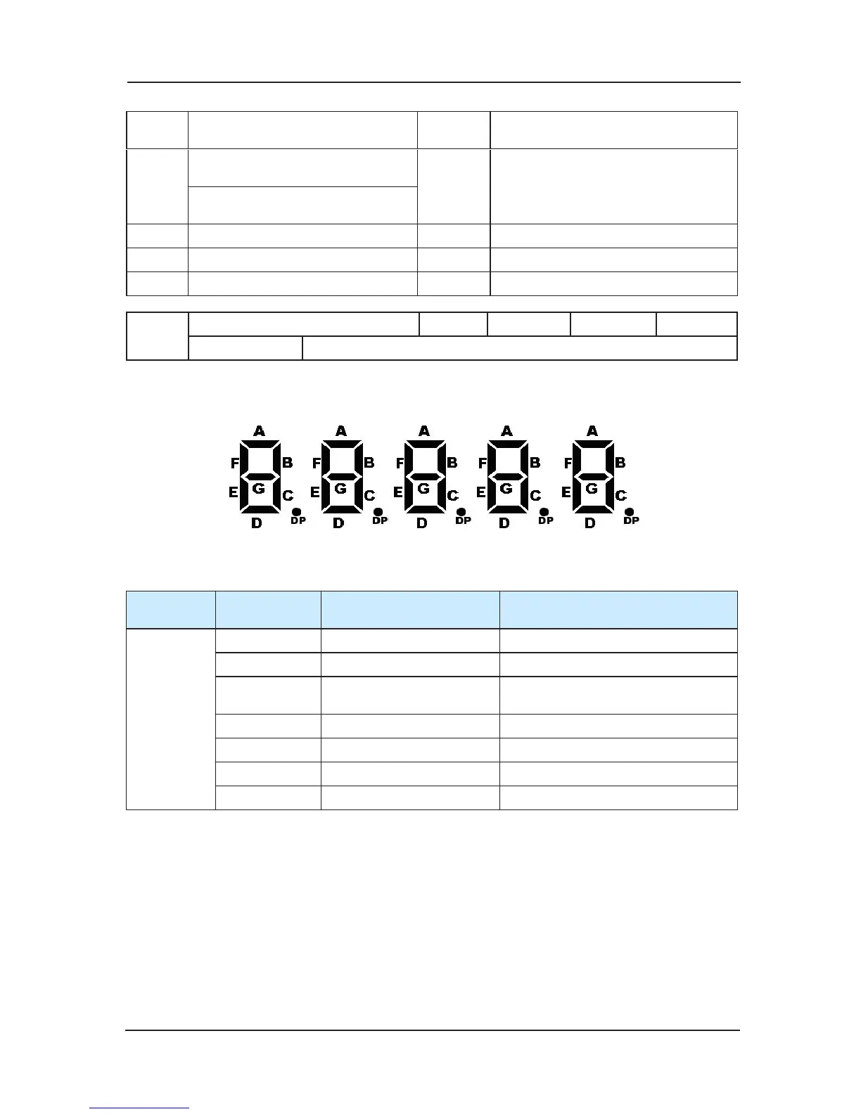
F5-34、F5-35 show the input and output terminal state. The keyboard tube order is 5, 4,3,2,1
from left to right. Every passage’s definition is as follows:
F5-34 expresses the state of the main control panel input or output terminal. Its meanings are
listed in the following charts:
Tube Serial
number
Tube passage
marker
Tube passage meaning Tube passage “light” meaning
B Up leveling Up leveling signal availability
C Down leveling Down leveling signal availability
D door zone signal
Door zone signal availability, at the
leveling station
E Safety circuit feedback 1 Safety circuit pass
F Lock circuit feedback 1 Lock circuit pass
G Run output feedback 1 Contactor close state
DP Brake
output feedback 1 Brake open state
 Loading...