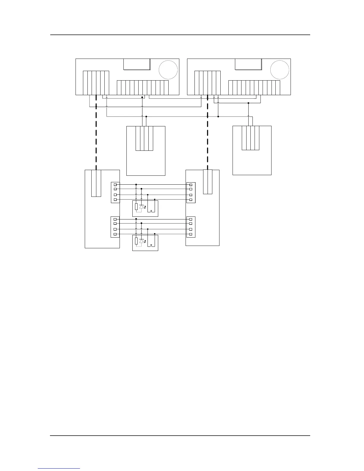
Fig 7-8 Parallel wiring
The chart shows the wiring mode of external call button and the wiring mode of parallel CAN
communication. When in using, the following items should be paid attention to:
Car top board dial setting1)
In parallel, the car top board’s dial switch of the main lift with the number 1 is the same with
it’s used in single lift, which means the first bit of Sw1 is on OFF position; the
car top board’s
dial switch of the subordinate lift with the number 2, Sw1’s first bit should be setting on ON
position; otherwise it will cause the abnormal data communication of the lift’s car top.
CAN communication net’s terminal resistance disposal2)
In parallel, the communication terminal resistances dial of two lifts’ car top control board
need to be switched to the “ON” position. The J5 on t
he main control board chooses not to
connect the terminal resistance (to connect the two pins above, when the small keyboard is on
the top, the method is not suitable for the VER A, VER B, VER C edition).In this way, there’s
terminal resistance only in the terminal car top board in CAN communication net.
Main control board relay output setting3)
In the above chart, the two lifts’ CAN+ of the CAN co
mmunication wiring is trans-connected
through the Y4-M4 on the main control board, which confirms the two lifts won’t affect each
other when the power is broken or other abnormal condition occurs. Therefore the following
 Loading...