3-56 ENGINE CONTROL SYSTEM
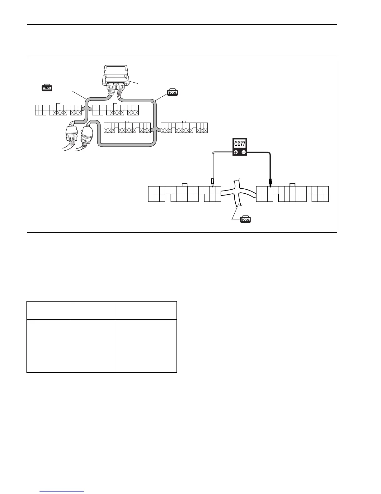
IGNITION COIL OPERATING SIGNAL
" 09930-89340: 26-pin & 34-pin test cord
Peak voltmeter Stevens CD-77
' Tester range: SEN 50
1. Connect test cord between ECM and wire harness as shown
in figure then turn ignition switch ON.
2. Connect the tester probe (“
+”, Red) to each terminal.
3. Connect the tester probe (“
-” Black) to No. 46 terminal (or
to body ground).
4. Crank engine and measure voltage.
Ignition coil operating signal: Approx. 5 V
Ignition coil Terminal
Wire color
(engine harness)
No. 1
No. 2
No. 3
No. 4
No. 5
No. 6
42
50
39
45
37
38
O
Bl
Gr/Y
Lg/R
W/G
Bl/Y
27
40
28
41
29
42
30 31
43
32 33 34 35 36 37 38 39 44
57
45
58
46
59
47 48
60
49 50 51 52 53 54 55 56
14 15 16 17 18 19 20 21 22 23 24 25 2612345678910111213
(White connector)
(White connector)
(White connector)
(Black connector)
(Black connector)
(Black connector)
34 pin test cord
26 pin test cord
ECM
34 pin test cord
4537
42
38 39 46 50