ENGINE CONTROL SYSTEM 3-55
FUEL INJECTOR OPERATING SIGNAL
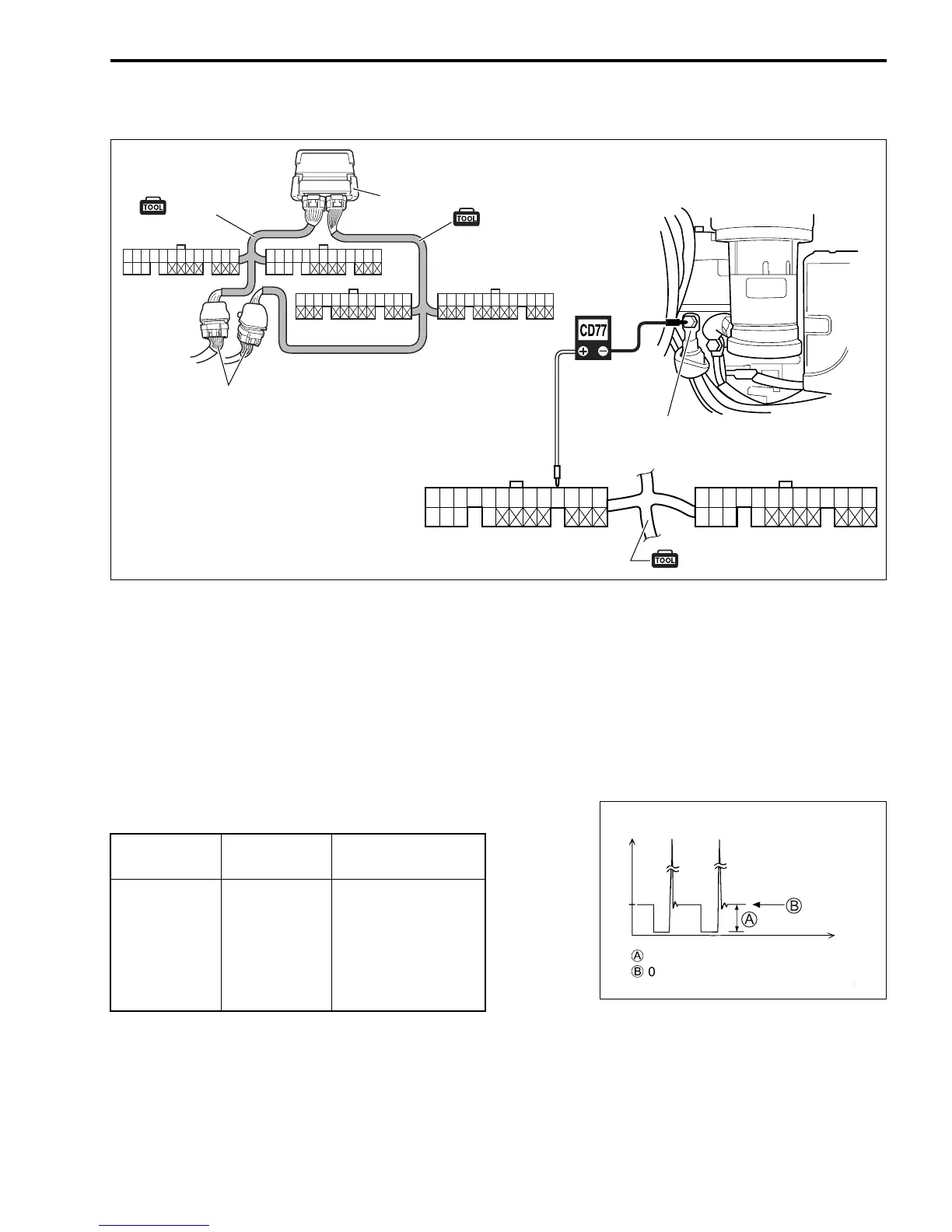
" 09930-89340: 26-pin & 34-pin test cord
Peak voltmeter Stevens CD-77
' Tester range: NEG 50
1. Connect test cord between ECM and wire harness as shown
in figure then turn ignition switch ON.
2. Connect the tester probe (“
-”, Black) to starter motor mag-
netic switch “B” terminal (connected to battery positive
+
terminal) as shown in figure.
3. Connect the tester probe (“
+”, Red) to each terminal.
4. Crank engine and measure voltage.
Fuel injector operating signal: 6 – 10 V
Starter motor magnetic
switch “B” terminal
34 pin test cord
27 28 29 36 53 54
27
40
28
41
29
42
30 31
43
32 33 34 35 36 37 38 39 44
57
45
58
46
59
47 48
60
49 50 51 52 53 54 55 56
14 15 16 17 18 19 20 21 22 23 24 25 2612345678910111213
(White connector)
(White connector)
(Black connector)
(Black connector)
34 pin test cord
26 pin test cord
ECM
Wire harness
(White connector)
(Black connector)
Injector Terminal
Wire color
(engine harness)
No. 1
No. 2
No. 3
No. 4
No. 5
No. 6
54
36
28
53
27
29
O/B
B/Br
R/W
Lg
O/Bl
Y/R
)
Peak voltage reading (NEG)
*
0 V level for peak voltmeter
(Voltage)
(Time)
12 V