ANTILOCK BRAKE SYSTEM (ABS) 5E2-3
General Description
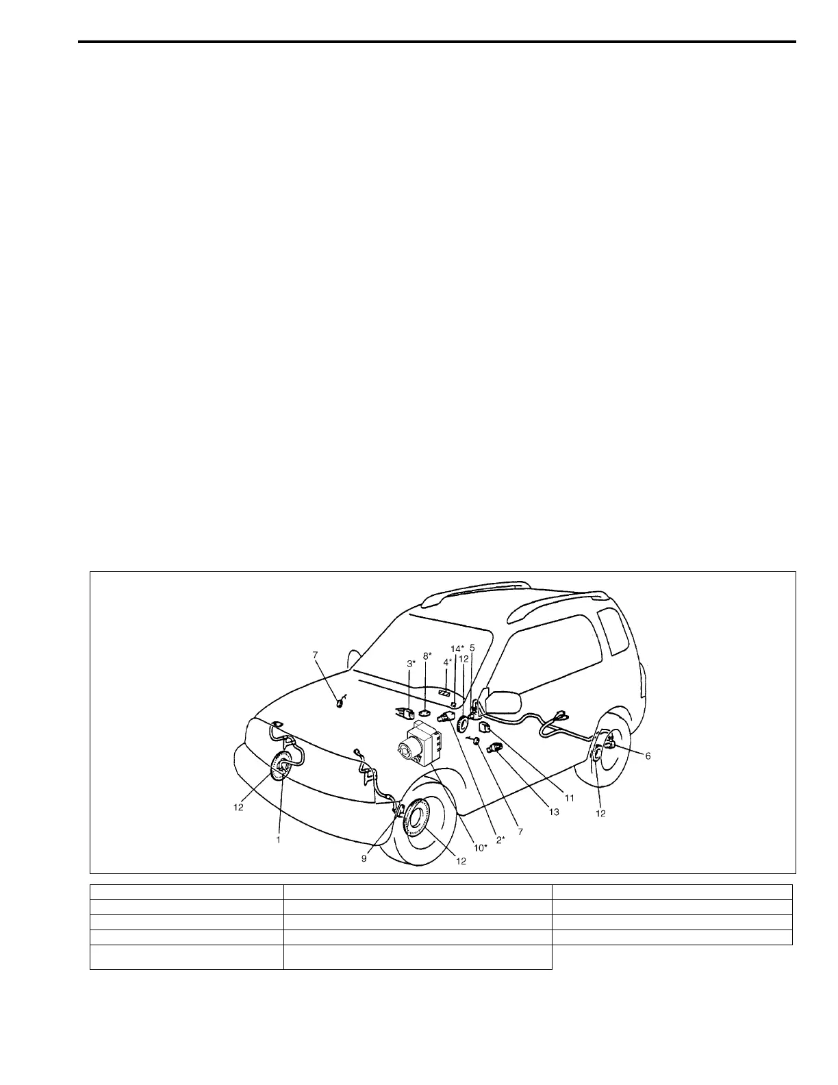
Components/Parts Location
The ABS (Antilock Brake System) controls the fluid pressure applied to the wheel cylinder of each brake from
the master cylinder so that each wheel is not locked even when hard braking is applied.
This ABS has also the following function.
While braking is applied, but before ABS control becomes effective, braking force is distributed between the
front and rear so as to prevent the rear wheels from being locked too early for better stability of the vehicle.The
main component parts of this ABS include the following parts in addition to those of the conventional brake sys-
tem.
• Wheel speed sensor which senses revolution speed of each wheel and outputs its signal.
• ABS warning lamp which lights to inform abnormality when system fails to operate properly.
• ABS hydraulic unit/control module assembly is incorporated ABS control module, ABS hydraulic unit (actua-
tor assembly), fail-safe relay and pump motor relay.
– ABS control module which sends operation signal to ABS hydraulic unit to control fluid pressure applied to
each wheel cylinder based on signal from each wheel speed sensor so as to prevent wheel from locking.
– ABS hydraulic unit which operates according to signal from ABS control module to control fluid pressure
applied to wheel cylinder of each 4 wheels.
– Fail-safe relay (solenoid valve) relay which supplies power to solenoid valve in ABS hydraulic unit and
pump motor relay.
– Pump motor relay which supplies power to pump motor in ABS hydraulic unit.
• G sensor which detects body deceleration speed. (For 4WD model only)
This ABS is equipped with Electronic Brake force Distribution (EBD) system that controls a fluid pressure of rear
wheels to best condition, which is the same function as that of proportioning valve, by the signal from wheel sen-
sor independently of change of load due to load capacity and so on. And if the EBD system fails to operate prop-
erly, the brake warning lamp lights to inform abnormality.
1. Wheel speed sensor (Right-front) 6. Wheel speed sensor (Left-rear) 11. G sensor (For 4WD model only)
2. Stop lamp switch 7. Ground 12. Wheel speed sensor rotor (ring)
3. Data link connector 8. Diagnosis connector (Black connector) 13. 4WD switch (For 4WD model only)
4. “ABS” warning lamp 9. Wheel speed sensor (Left-front) 14. EBD warning lamp (Brake warning lamp)
5. Wheel speed sensor (Right-rear) 10. ABS hydraulic unit/control module assembly
(with ABS pump motor relay and fail-safe relay)
NOTE:
Above figure shows left-hand steering vehicle.
For right-hand steering vehicle, parts with (*) are installed at the side of symmetry.
 Loading...


