ANTILOCK BRAKE SYSTEM (ABS) 5E2-27
DTC C1063 (DTC 63) – ABS Fail-Safe Relay Circuit
DESCRIPTION
ABS control module monitors the voltage at the terminal of solenoid circuit constantly with ignition switch turned
ON. Also, immediately after ignition switch is turned ON, perform initial check as follows.
Switch fail-safe relay in the order of OFF → ON and check if voltage changes to Low → High. If anything faulty is
found in the initial check and when the voltage is low with ignition switch turned ON, this DTC will be set.
INSPECTION
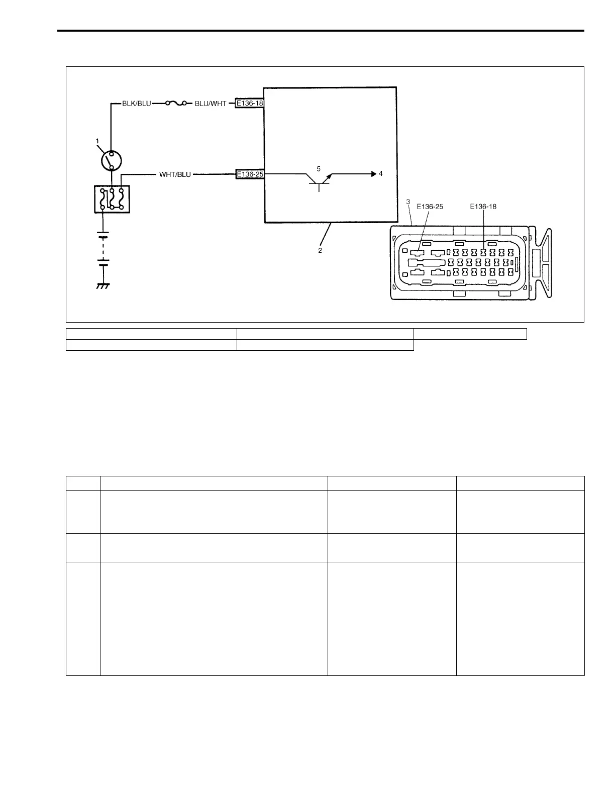
1. Ignition switch 3. ABS hydraulic unit/control module connector 5. Fail-safe relay
2. ABS hydraulic unit/control module assembly 4. To solenoid valves
Step Action Yes No
1 Check battery voltage. Is it about 11 V or
higher?
Go to Step 2. Check charging system
referring to “CHARGING
SYSTEM” section.
2 Check ABS main fuse and connection.
Is it in good condition?
Go to Step 3. Repair and/or replace
fuse.
3 1) Ignition switch OFF.
2) Disconnect ABS hydraulic unit/control mod-
ule connector.
3) Check proper connection to ABS hydraulic
unit/control module at terminal “E136-25”.
4) If OK, then measure voltage between con-
nector terminal “E136-25” and body ground.
Is it 10 – 14 V?
Substitute a known-good
ABS hydraulic unit/con-
trol module assembly and
recheck.
“WHT/BLU” circuit open
or short to ground.
 Loading...


