7B1-54 AUTOMATIC TRANSMISSION (4 A/T)
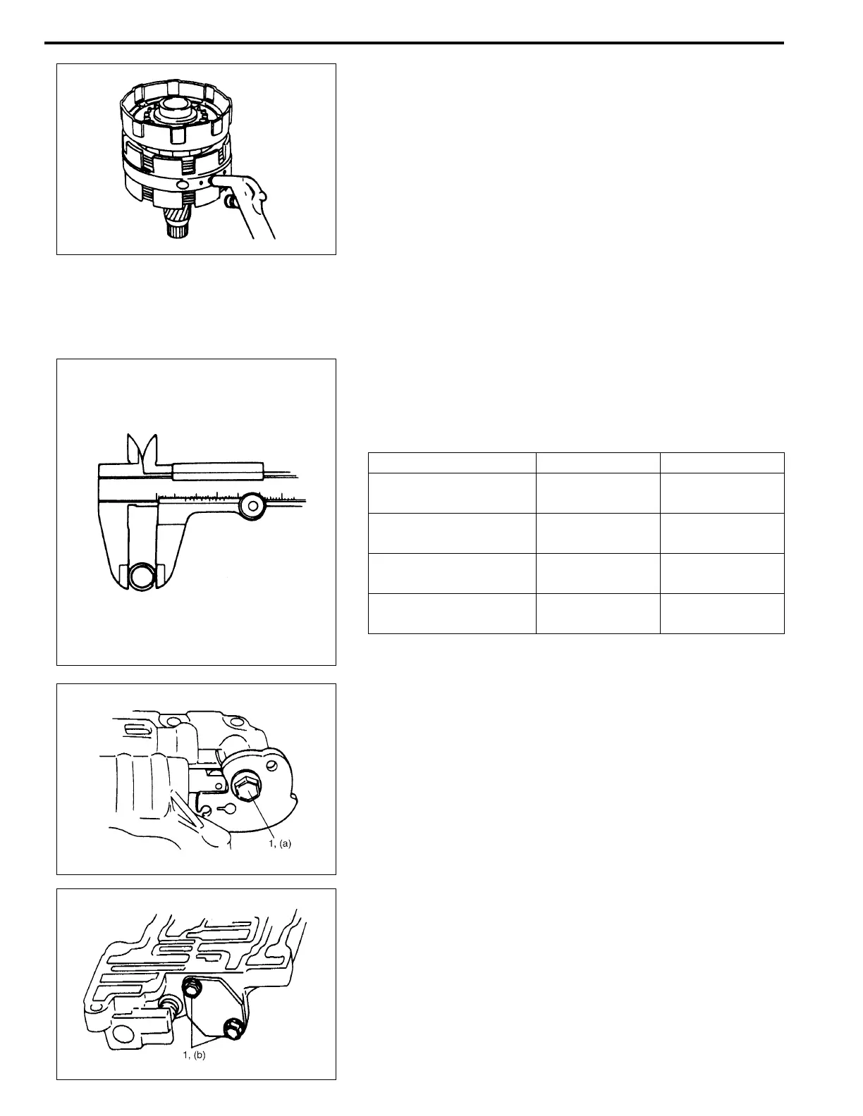
6) Install direct clutch cylinder to center support.
Remove direct clutch piston by blowing air into the second
hole from the left as shown in the figure. Also, remove direct
clutch inner piston by blowing air into hole at the extreme
right. And then remove O-rings from pistons.
Front upper valve body
ASSEMBLY
Assemble each component by reversing disassembly procedure
and noting the following points.
• Coil outer diameter and free length of each valve spring
should be as listed below. Be sure to use each one of correct
size.
Coil outer diameter and free length of each valve spring
• Install as many throttle valve compensating rings as written
down when disassembled.
• Tighten throttle cam bolt (1) to specified torque.
Tightening torque
Throttle cam bolt (a) : 7.5 N·m (0.75 kg-m, 5.5 lb-ft)
• Tighten pressure relief valve bolts (1) to specified torque.
Tightening torque
Pressure relief valve bolt (b) : 5.5 N·m (0.55 kg-m, 4.0 lb-ft)
Name of spring Outer diameter Free length
Secondary regulator
valve spring
17.43 mm
(0.681 in.)
71.27 mm
(2.806 in.)
Cut back valve spring 6.85 mm
(0.259 in.)
23.0 mm
(0.906 in.)
Throttle valve
secondary spring
8.56 mm
(0.337 in.)
18.86 mm
(0.743 in.)
Throttle valve
primary spring
10.90 mm
(0.429 in.)
39.55 mm
(1.557 in.)
 Loading...


