ABS: 4E-22
10 1) Turn the ignition switch OFF.
2) Remove the left frame cover. Refer to “Exterior Parts
Removal and Installation (GSF650/S/A/SAK7) in Section
9D (Page 9D-6)”.
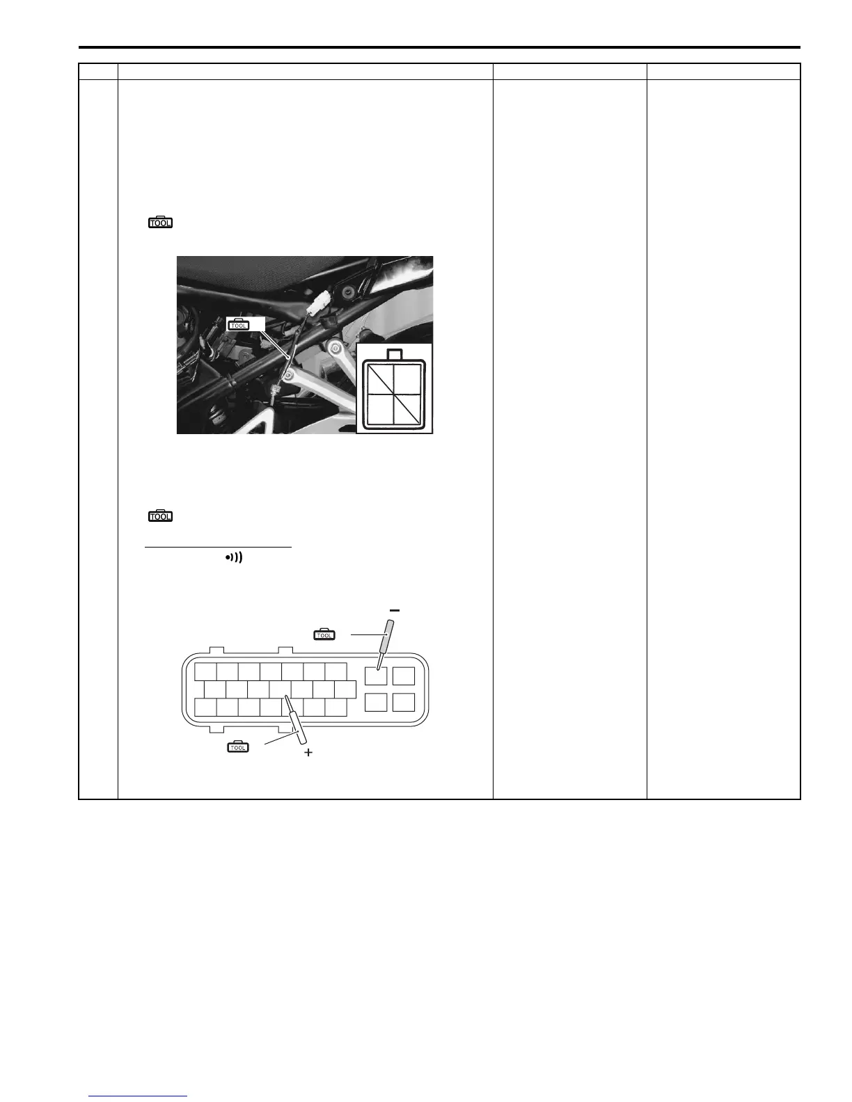
3) Short the mode select coupler terminals (O – B/W) using
the special tool.
Special tool
(A): 09930–82710 (Mode select switch)
4) Check for continuity between “13” (O) and “24” (B/W) at
the coupler.
Special tool
(A): 09900–25008 (Multi-circuit tester set)
Tester knob indication
Continuity ( )
ABS control unit coupler (Harness end)
Is there continuity between “13” and “24”?
Replace the ABS
control unit/HU.
Inspect the wire
harness. (Faulty mode
select switch wire)
Step Action Yes No
(A)
O
B/W
I718H1450042-03
24 25
(ޓ)
18
10
12 13
16
2
3
4
21
(ޓ)
89
(A)
(A)
I718H1450043-02
 Loading...