INSIDE COMPONENTS AND ELECTRONICS | COUPLER TUBE AND BRAKE MOTOR (BRAKE ACTUATOR ASSEMBLY)40
APR/2017 TECHNICAL OPERATIONS AND MAINTENANCE GUIDE | NEXUS STATION
2 Locate the end of the power harness—labeled P16—at the lower-right corner of the main circuit
board, and carefully detach it from the circuit board.
3 Loosen the three screws that attach the bracket to the back station wall. Slide the back bracket
slightly to the right so the screws can slide through the larger end of the keyhole openings. Then
remove the bracket from the screws and out of the station.
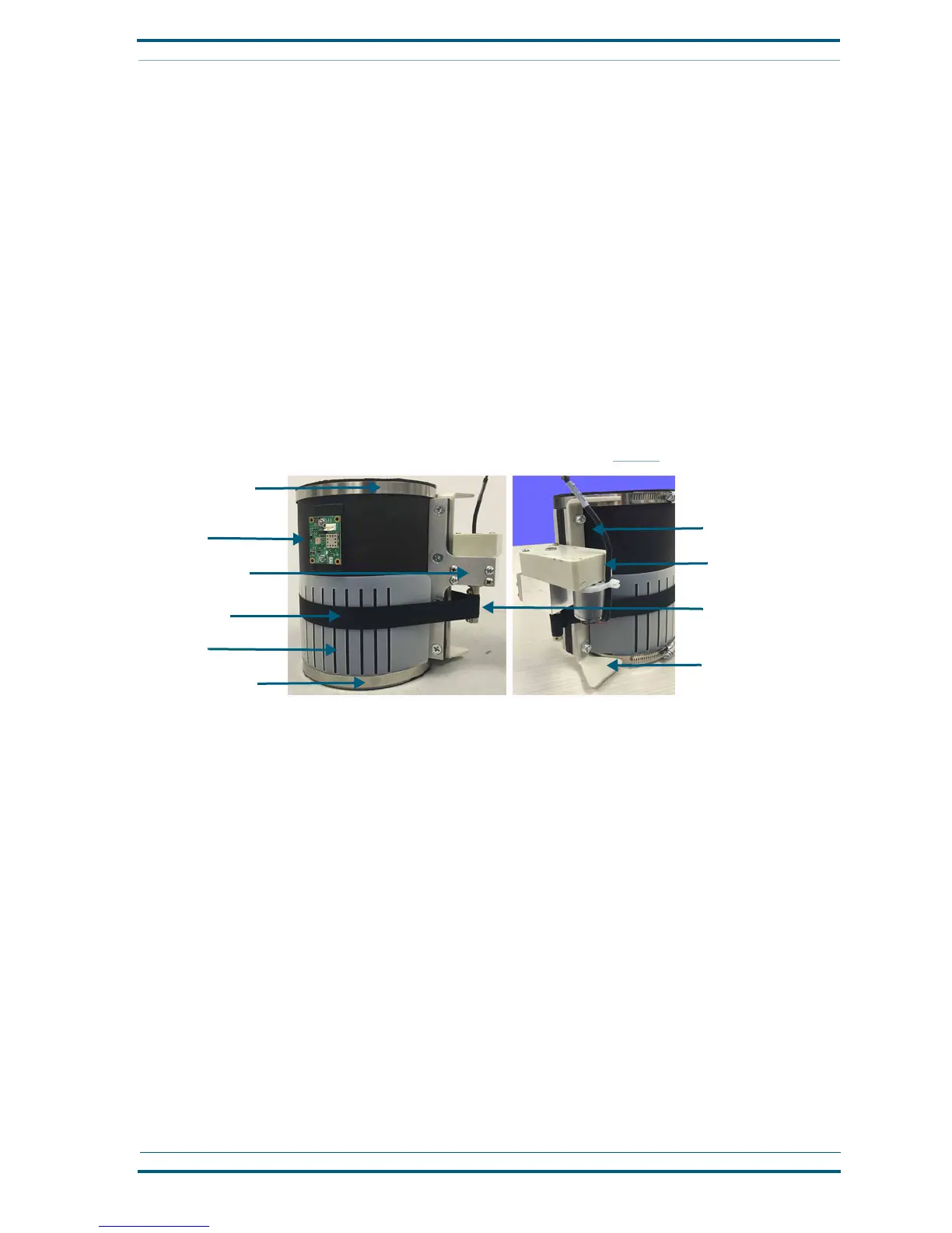
Coupler tube and brake motor (brake actuator assembly)
A rubber tube assembly fits over the ends of the existing send-receive tube and motor-plate tube to provide
the entry and exit point for carriers being delivered to and sent from the Nexus Station. It includes a carrier
sensor, along with a brake that is attached to the rubber tube with an adjustable nylon strap that retracts
when the brake is engaged to slow the descent of a carrier into the station.
The coupler tube and motor (brake actuator) or parts of it can be removed when being repaired or
replaced. It must be taken apart to be installed back into the station.
The nylon strap and plastic collar can be removed and replaced without removing the full tube assembly
and motor from the station.
If you are replacing a brake strap and/or collar only, skip to step 5 on
page 41.
Follow these steps to attach the brake assembly to the send-receive pipes.
1 Begin installing the tube into the station. With the electronic sensor facing forward and the connec-
tion end to the right, wrap the rubber tube around the upper and lower tubes. Place the opening
about three inches in front of the outlet box.
2 As you hold the tube, loosen the upper and lower metal bands and slide them around the top and
bottom edges of the tube. Then tighten the bands until they hold the tube in place. Do not securely
attach them yet.
3 Add the two long metal brackets where the sides of the tubes connect, placing the curved edges of
the brackets inward and the motor bracket at the front. Hold the brackets and tube edges together as
you tighten the bolts from the front bracket, through the tube edges, and through the back bracket.
Motor brackets
Collar
Adjustable band
Motor
Brake strap
Sensor
Adjustable band
Brake controller
Stabilizing bracket
Stabilizing bracket
 Loading...