INSIDE COMPONENTS AND ELECTRONICS | UPPER AIR MANIFOLD (SLIDE-GATE COVER)44
APR/2017 TECHNICAL OPERATIONS AND MAINTENANCE GUIDE | NEXUS STATION
2 Hold the ribbon tightly as you flip the switch to turn on the station, and continue grasping it as the
ribbon squeezes the rubber tube, tightens the ribbon, and then adjusts to its proper placement on the
collar, as shown.
3 Turn on the power switch at the back of the station, and allow the station to boot up.
Verify that the station boots up and is operational before continuing. The screen that appears upon
boot-up indicates that the station requires commissioning, as shown next.
4 The turnstile may turn to the left and right a few times in an attempt to align itself. Wait to perform
the next step until the turnstile has stopped moving.
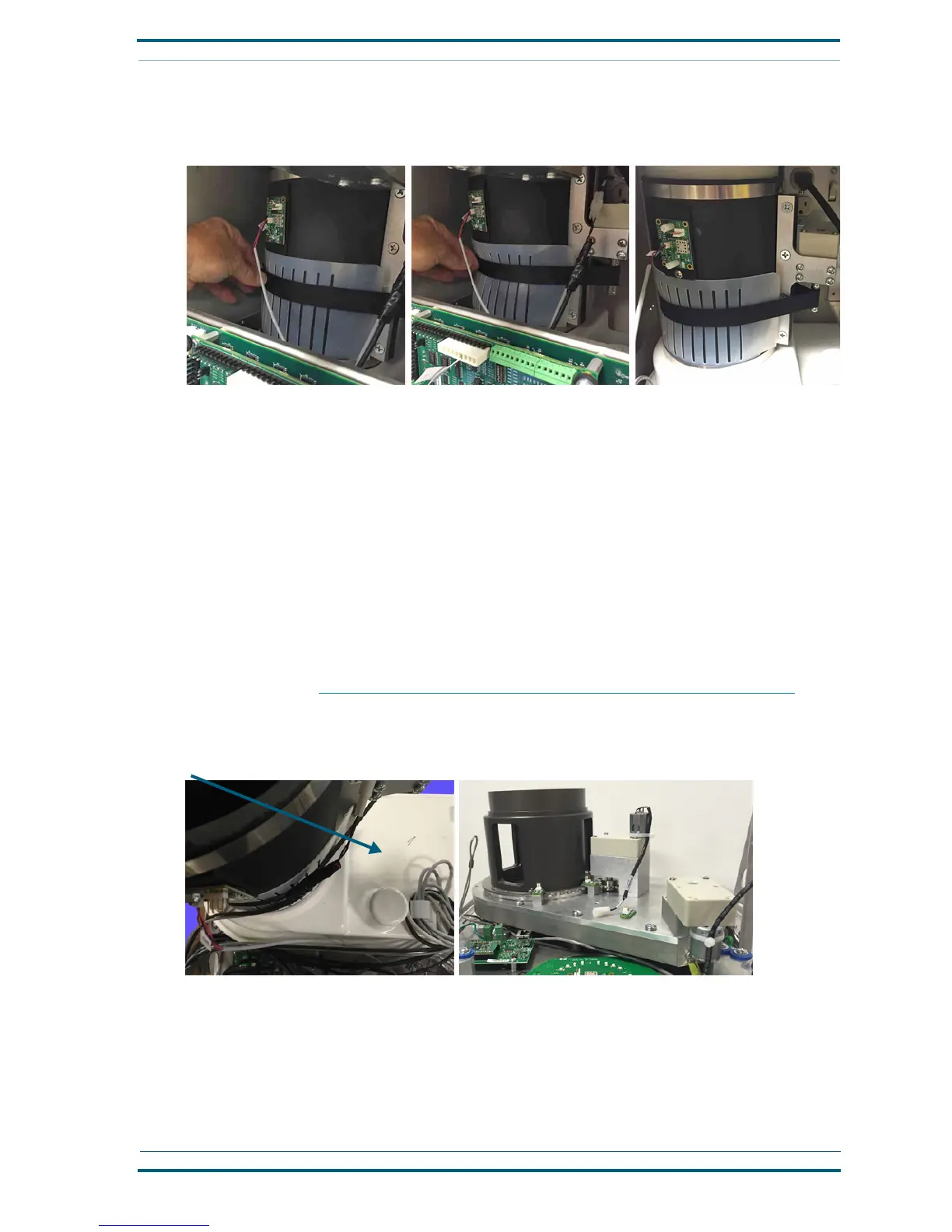
Upper air manifold (slide-gate cover)
The upper air manifold, or slide-gate cover, requires removal to expose the air valve on earlier versions of the
Nexus Station. Remove the manifold to lubricate the air valve or gear or check the air valve in the event of a
problem. The protective cover is attached with several small Phillips screws positioned around the outside
edge.
The coupler tube and brake motor must be removed before the upper air manifold can be removed from
around the valve assembly. See “Coupler tube and brake motor (brake actuator assembly)” on page 40.
Loosen and remove the Phillips screws around the outer edge of the protective cover/air manifold.
Then lift it from the valve assembly.
Front motors: pin actuator and security-door actuator
Both the security-door actuator and the pin actuator must be removed from the front of the turnstile
assembly before the turnstile can be removed from the station. They can be reattached after the turnstile
has been placed back into the station. Remove the harness attachments before removing the motors.
Remove the protective cover
Exposed valve assembly
 Loading...