NEXUS STATION | TECHNICAL OPERATIONS AND MAINTENANCE GUIDE APR/2017
43 INSIDE COMPONENTS AND ELECTRONICS | COUPLER TUBE AND BRAKE MOTOR (BRAKE ACTUATOR ASSEMBLY)
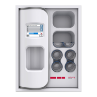
tube with the sensor attachment. Then place one metal band over the lower pipe that attaches to the
core assembly and the other metal band to the upper pipe that connects the station to the tube sys-
tem. Tighten the band around the upper pipe until it stays fastened.
Having the bands in position is helpful when you reinstall the tube.
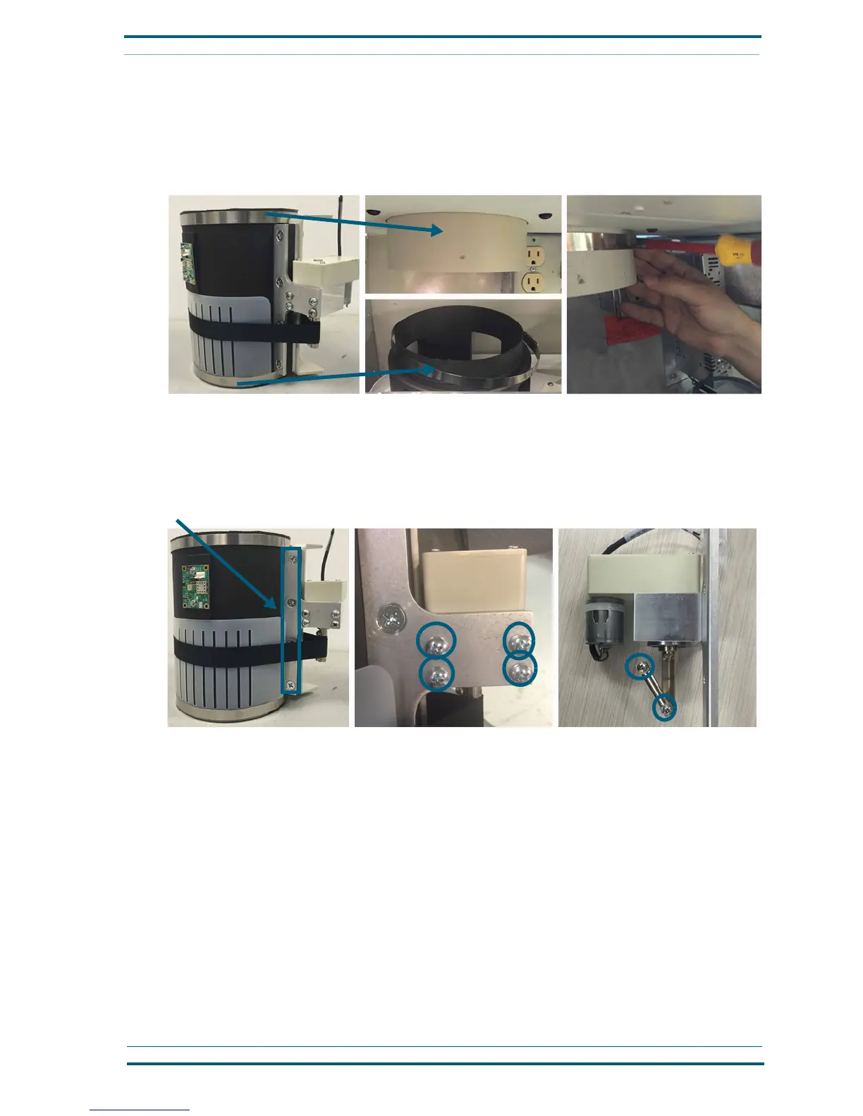
2 Remove the coupler-motor from the brake assembly. With the no. 2 Phillips screwdriver and a
7
/
16
-inch
socket ratchet,
remove the four nuts and bolts that attach the motor bracket to the tube. Then remove
the four screws from the center portion of the bracket where the motor is attached. Finally, with a no.
1 Phillips screwdriver, remove the two screws on the coupler stem to disengage the black fabric strap
from the coupler assembly.
Calibrate the brake
The brake requires calibration when it is first installed or when the strap and collar have been replaced. You
can begin the calibration process when the strap is loosely in place on the brake controller.
Follow these steps to calibrate the brake.
1 Reach into the top of the station, behind the circuit board, and grasp the ribbon surrounding the
brake collar so that the ribbon is taut and parallel to the top edge of the collar, about 1
1
/
2
inches
down, as shown next.
The ribbon should be placed in a straight line from where it is attached to the stem on the brake
motor, as shown.
Attach metal bands to the upper and lower pipes
Remove the bracket from the tube
Remove the motor from the coupler
Remove the bracket and strap
 Loading...