NEXUS STATION | TECHNICAL OPERATIONS AND MAINTENANCE GUIDE APR/2017
77 SEQUENCE FOR TROUBLESHOOTING NEXUS STATION COMPONENT ERRORS | REFERENCE DIAGRAMS
Signal diodes
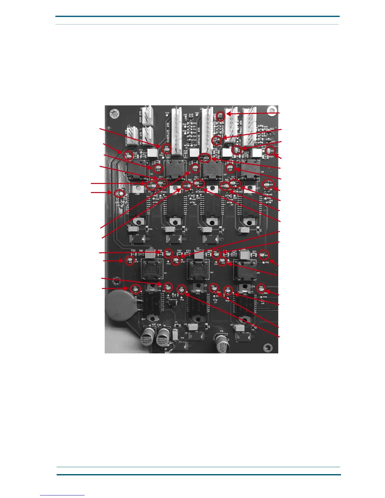
Locations of the signal diodes for the primary Nexus Station components are shown in the next illustration.
Use this illustration to locate the diodes that will help you determine whether a communications signal is
traveling between the circuit board and the affected component. The diodes work in pairs, usually to indi-
cate position and/or movement of the component, such as open/closed, up/down, left/right, locked/
unlocked, clockwise/counter-clockwise. The individual component sections provide more detail
Locations of signal LEDs on the main circuit board for the Nexus Station
D51 Air valve e-o-t closed
D50 Air valve e-o-t, open
D33 Pin actuator motor
D32 Pin actuator motor
D34 Pin actuator locked
D35 Pin actuator unlocked
D25 Slide plate motor
D24 Slide plate motor
D36 Brake actuator
D37 Brake actuator
D28 Air valve motor
D38 Brake actuator
D39 Brake actuator
D30 Air valve signal
D26 Slide plate
D27 Slide plate
D14 Pin act. motor
D15 Pin act. motor
D12 Push act. signal
D13 Push act. signal
D19 Turnstile act. motor
D18 Turnstile act. motor
D22 Security door actuator
D23 Security door actuator
D20 Security door actuator
D21 Security door actuator
D16 Turnstile act. signal
D17 Turnstile act. signal
D29 Air valve motor
D31 Air valve signal
 Loading...