NEXUS STATION | TECHNICAL OPERATIONS AND MAINTENANCE GUIDE APR/2017
83 INSTRUCTIONS FOR TROUBLESHOOTING COMMON COMPONENT ERRORS | TURNSTILE ERRORS
Push-rod errors
The most common push-rod errors result from the rod having failed to extend or retract. The initialization
and extend/retract errors are all investigated in the same way.
Push-rod extend / retract / initialization failure
Follow the steps outlined in the table to investigate errors involving the push-rod.
No. Error Description
4096
4097
Push rod did not extend / retract The push actuator has failed to extend or retract in either a receipt or dispatch
operation.
4098 Push-rod not initialized Similar to the retract and extend errors, when the station is started and the
push-rod fails to move through its full range of motion, or the station cannot
detect its position, this initialization error may occur, followed by an extend or
retract error.
4210 Push-rod over-current The over-current advisory is not uncommon and does not stop the station’s
operation. If over-current errors become frequent, changing the push-rod
motor can decrease the frequency of advisories.
TABLE 5. Troubleshoot Nexus Station push-rod errors
Action | component Details | expected condition | next steps
1 Inspect power harness PCB connections Push-rod motor–J7; push-rod encoder–J28
2 Observe LED signal indicators Motor on/off–D14/D15; Motor driver–D12/D13
3 Inspect pin actuator connections and verify that
it is operational. See Turnstile errors.
Pin actuator is operational, and turnstile is in locked posi-
tion with the front compartment aligned evenly between
the two sides of the security door.
If the pin actuator is not operational, follow the instruc-
tions for determining the cause of errors. Sometimes a
mis-alignment of the turnstile can also cause a push-
rod failure.
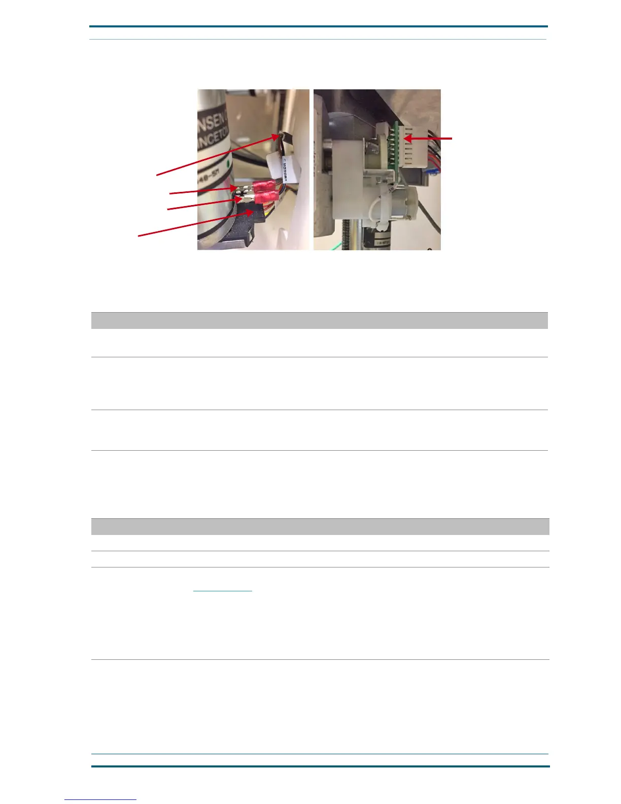
FIGURE 3. Troubleshoot Nexus Station turnstile errors
“TE” harness
“CMotor1” harness
Black wire connection
Brown wire connection
Pin actuator encoder prop-
erly connected with bracket
oriented so that encoder is
fully upright.
 Loading...