3. Theory of Operation
Simplified Functional Description
127
Simplified Functional Description
This section provides the simplified functional description of the 5071A
Primary Frequency Standard. The 5071A provides extremely accurate and
stable sine-wave outputs that are within five to ten parts in 10
13
of the
internationally accepted definition of frequency. The organization of the six
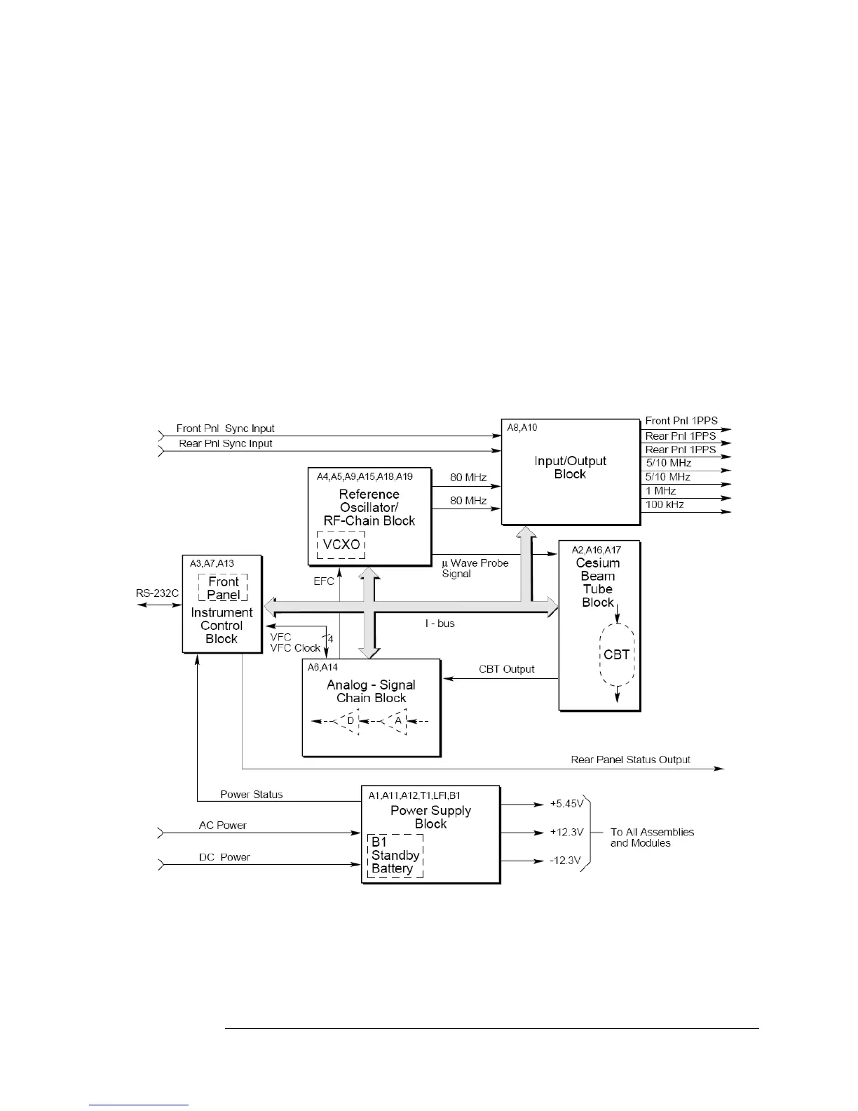
blocks within the instrument
is shown in Figure 3-1. They are:
1. Instrument control; A3, A7, A13, and Instrument bus (I-bus)
2. Reference oscillator/RF chain; A4, A5, A9, A15, A18, and A19
3. Cesium Beam tube; A2, A16, and A17
4. Analog-signal chain; A6, and A14
5. Input/output; A8, and A10
6. Power distribution; A1, A11, A12, LF1, T1, and B1(non-Opt. 048)
* Opt. 048 do not have Standby Battery
Figure 3-1. 5071A Simplified Block Diagram
 Loading...

