3. Theory of Operation
Functional Block Descriptions
143
Input/Output Block
The input/output block consists of the A8 1PPS assembly and A10 Output
Frequency Distribution Amplifier module. This block has five inputs and nine
outputs.
A10 receives an 80-MHz sine-wave signal from A9, SEL-A, and SEL-B select
inputs from A7 via the I-bus which are used to create the 5/10-MHz
programmable outputs for ports 1 and 2 along with fixed 1-MHz, and 100-kHz
outputs routed to the appropriate rear panel connectors.
A8 has four inputs and five outputs. An 80-MHz input from A9 is used with I-
bus command I/O to generate:
a. 1-MHz system clock signal sent to A2, 4, 6, and 7, and
b. two rear panel/one front panel 1PPS outputs.
Also, front- and rear panel Sync input signal connectors are used with I-bus
command signals to synchronize the instrument's 1 pps outputs to external
events and systems
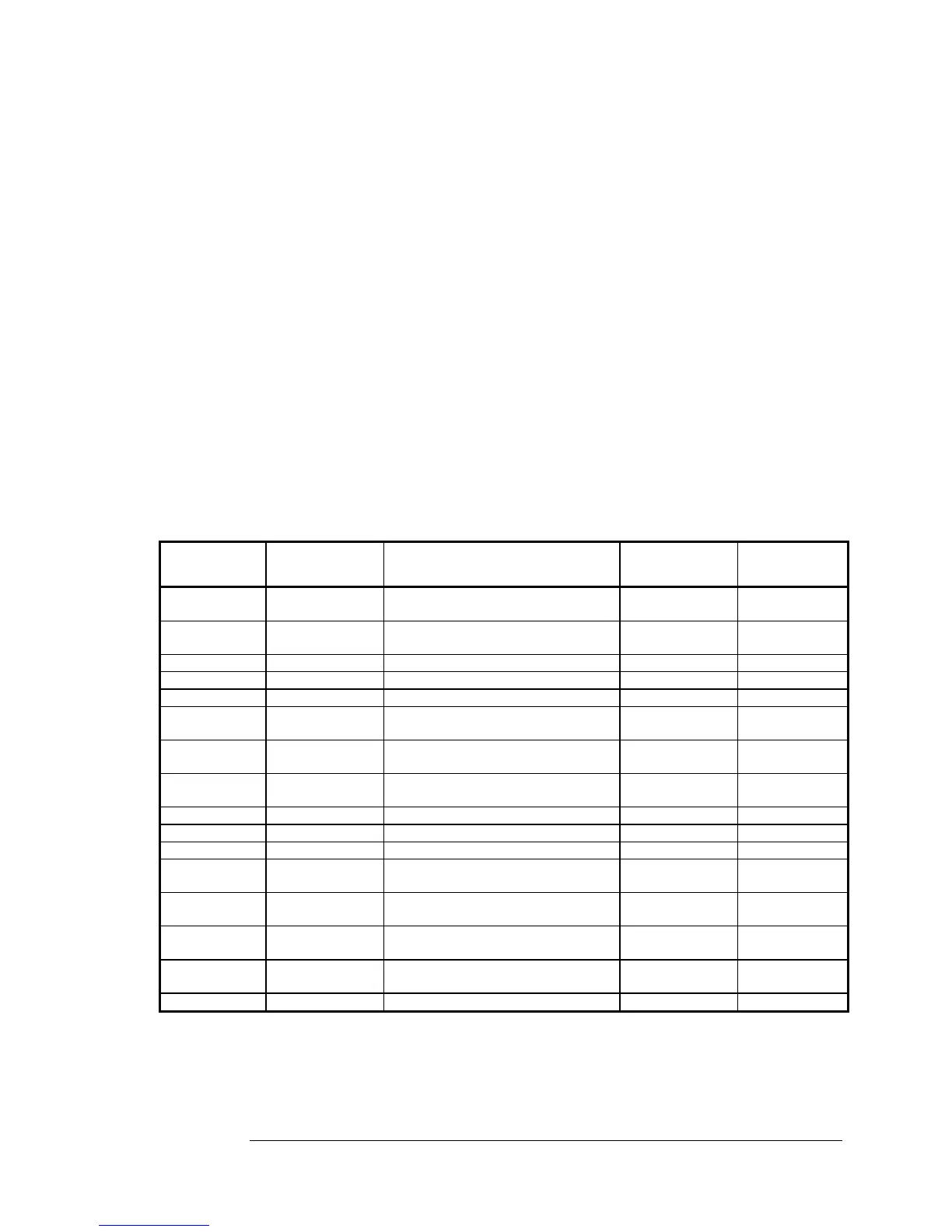
Table 3-5. Input/Output Block Interconnections
Source Mdl
or Assy
From Path
Connectors
Signal Name
(Connector Pin # in italics)
To Path
Connectors
Destination
Mdl or Assy
Sync Input,
Front Panel
A1J17 Sync Input XA8J2
10/11/12
A8
Sync Input,
Rear Panel
A1J15 Sync Input XA8J2
42/43/44
A8
A9 A9J4 80 MHz Input A8J3 A8
A8 XA8J2 16/48 1 MHz Internal Bus Clock XAnJ2 16/48 A2, 4, 6, 7
A8 XA8J1 44 1 PPS Output XA3J1 44 A3
A8 XA8J2
36/37/38
1 PPS Output (3) A1J14 1PPS Output,
Front Panel
A8 XA8J2 7/8/9 1 PPS Output (3) A1J16 1PPS Output,
Rear Panel
A8 XA8J2 4/5/6 1 PPS Output (3) A1J18 1PPS Output,
Rear Panel
A9 A9J2 80 MHz Input A10J5 A10
A7 XA7J2 8 SEL-A (~PD0) A1J7 A10
A7 XA7J2 9 SEL-B (~PD1) A1J7 A10
A10 N/A 5/10 MHz Programmable Output Module Internal Port 1,
Rear Panel
A10 N/A 5/10 MHz Programmable Output Module Internal Port 2,
Rear Panel
A10 N/A 1 MHz Output Module
Internal
1 MHz,
Rear Panel
A10 N/A 100 kHz Output Module Internal 100 kHz,
Rear Panel
A3 XA3J1&2 I-bus (Instrument Bus) XA8J1&2 A8
 Loading...

