EasyManuals Logo

Symmetricom 5071A Assembly And Service Manual

Symmetricom 5071A
202 pages
To Next Page IconTo Next Page
To Previous Page IconTo Previous Page
Page #158 background imageLoading...
Page #158 background image
3. Theory of Operation
Functional Block Descriptions
142
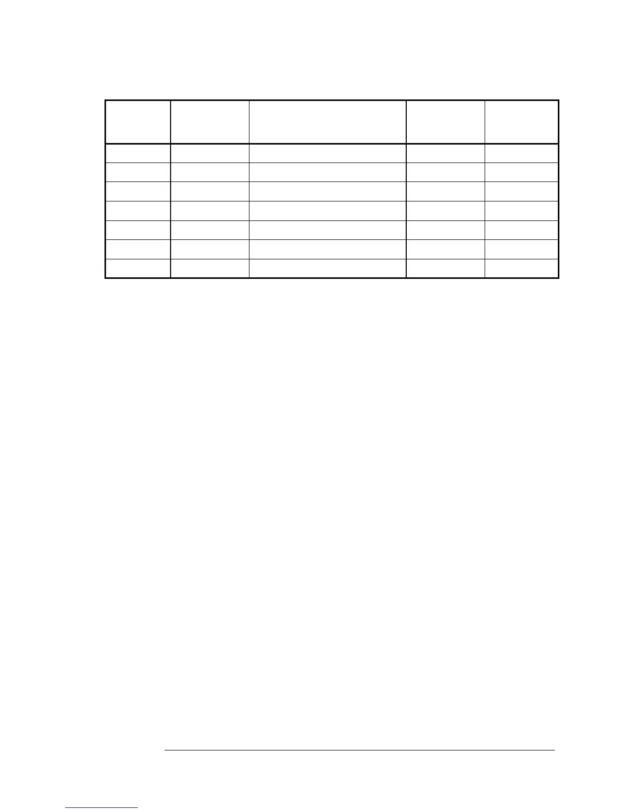
Table 3-4. Analog Signal Chain Block Interconnections
Source
Module or
Assembly
From Path
Connectors
Pin # in italics
Signal Name
To Path
Connectors
Pin # in italics
Destination
Module or
Assembly
A17 A17P1 CBT Output A14J1 A14
A14 A14J2 A14 Vout A6J3 A6
A6 XA6J2 12/44
VFC (2, VFCP)
XA3J2 12/44 A3
A3 XA3J2 13/45
VFCclock (2, 0.5 MHz)
XA6J2 13/45 A6
A6 A6J5 EFC (2, EFC/REFC) A19J11 39/40 A19
A6 XA6J2 39/40
A19 Power (2, VCXO)
A1J11 A19
A3 XA3J1&2 I-bus (Instrument Bus) XA6J1&2 A6

Table of Contents

Other manuals for Symmetricom 5071A

Questions and Answers:

Question and Answer IconNeed help?

Do you have a question about the Symmetricom 5071A and is the answer not in the manual?

Symmetricom 5071A Specifications

General IconGeneral
BrandSymmetricom
Model5071A
CategoryMeasuring Instruments
LanguageEnglish

Related product manuals