3. Theory of Operation
Functional Block Descriptions
134
The rear-panel Status Output provides a way to monitor instrument operation.
In default mode it tells when the front-panel continuous-operation LED turns
off. This output is SCPI command programmable via RS-232C port to go
active with other combinations of internal instrument events.
The I-bus consists of data, address, synchronization, power, and dedicated
hardware signal lines that together provide the main control and information
pathway within the instrument.
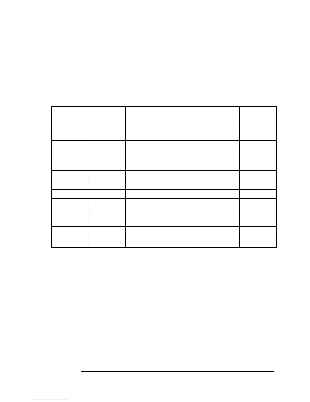
Table 3-1. Instrument Control Block Interconnections
Source
Module or
Assembly
From Path
Connectors
Pin # in italics
Signal Name
To Path
Connectors
Pin # in italics
Destination
Module or
Assembly
A3 XA3J1
60/61/62
RS-232C (3) A1J6 Rear Panel
A3 XA3J2
14/46
Strobe (2, RTDS)
XA4J2 14/46
XA6J2 14/46
XA7J2 14/46
A4
A6
A7
A11 A11P102 Power Status (4, via A1J3)
XA3J1
26/27/28/58
A3
A6 XA6J2 14/44
VFC (2, VFCP)
XA3J2 12/44 A3
A3 XA3J2 13/45 VFCclock (2, 0.5 MHz) XA6J2 13/45 A6
A7 XA7J2 11 Amplitude Modulation (IAT) A15J1 to A1J19 A15
A7 XA7J2 10 C-Field Control (CFC) XA2J2 10 A17 (via A2)
A7 XA7J2 43 Status Output (~PD5) A1J6 2 Rear Panel
A3 A3J1 79-95 A3 - A13 bus cable A13J1 to A1J13 A13
A3 XA3J1&2 I-bus (Instrument Bus)
A1 Global,
All Slots
All Bussed
Assemblies
and Modules
 Loading...

