3. Theory of Operation
Functional Block Descriptions
140
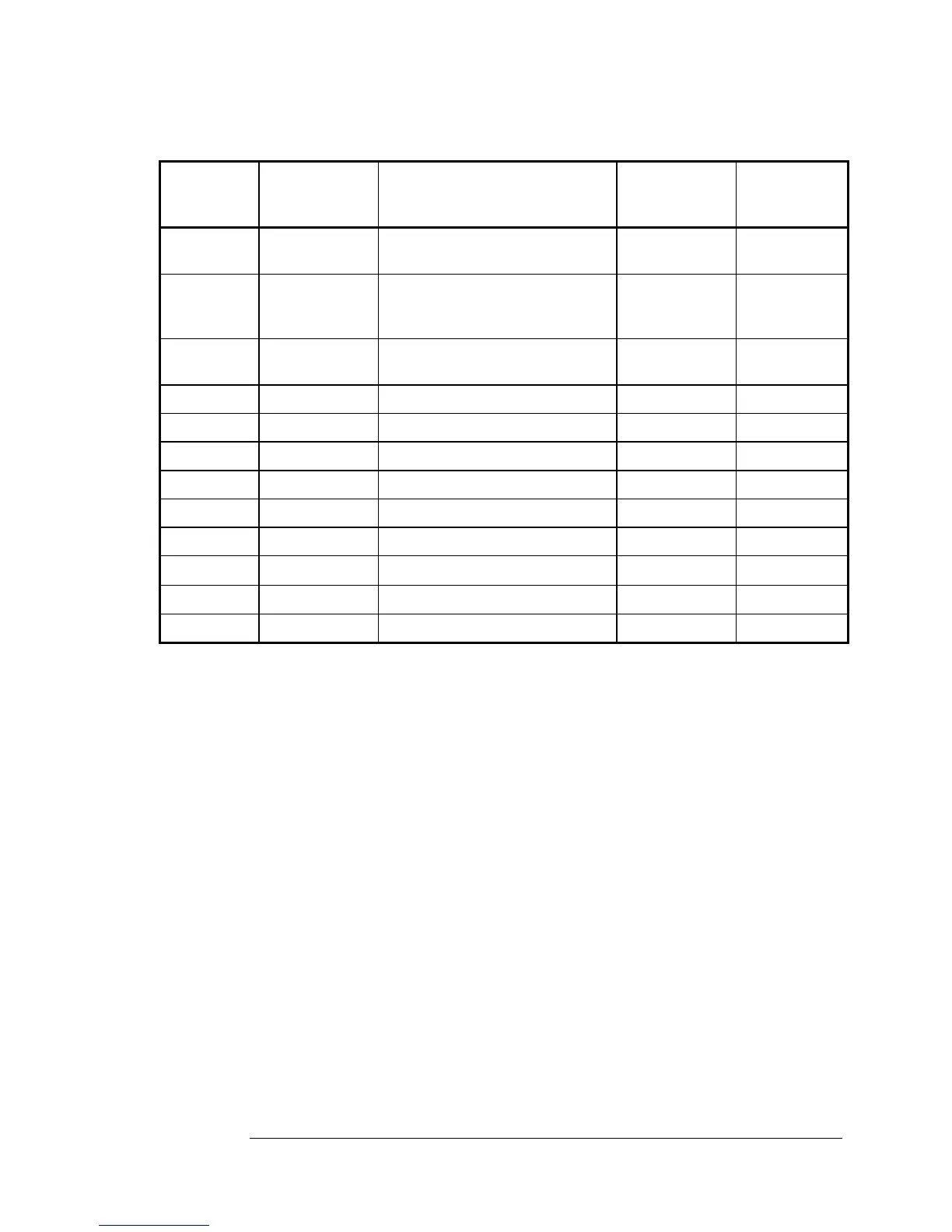
Table 3-3. Cesium Beam Tube Block Interconnections
Source
Module or
Assembly
From Path
Connectors
Pin # in italics
Signal Name
To Path
Connectors
Pin # in italics
Destination
Module or
Assembly
A2 XA2J1
28/29/30
Control/Monitor (3) A1J12 A16
A16 Long White
HV lead
Ion Pump Right-hand
CBT HV
socket
A17
A16 Short-White
HV lead
Electron Multiplier Left-hand CBT
HV socket
A17
A7 XA7J2 10 C-Field Control (CFC) XA2J2 10 A2
A2 A2J2 C-Field Control A17P3 A17
A2 A2J2 Thermistor A17P3 A17
A2 A2J2 Mass-Spectrometer A17P3 A17
A2 A2J1 Hot-Wire Ionizer A17P4 A17
A2 A2J2 Cesium Oven A17P3 A17
A15 A15J5
Wave Probe Signal ~9 GHz
A17 Adapter A17
A17 A17P1 CBT Output A14J1 A14
A3 XA3J1&2 I-bus (Instrument Bus) XA2J1&2 A2
 Loading...

