APPENDIX C
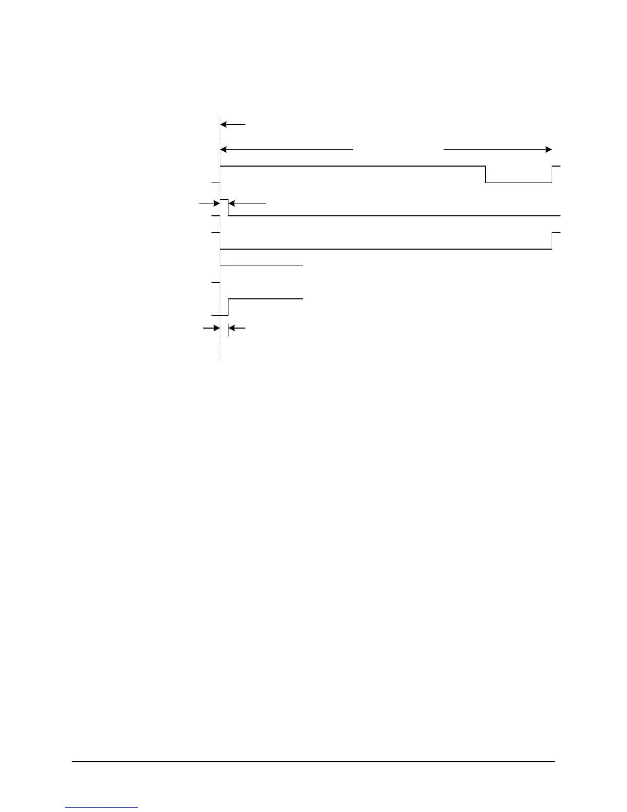
SAMPLE TIME PULSES:
CONNECTOR PIN 48 (ST1K)
CONNECTOR PIN 38 (ST1P)
ON TIME POINT
1 MILLISECOND
40 MICROSCEOND PULSE WIDTH OF ST1P
CONNECTOR PIN 1 (mS1)
CONNECTOR PIN 48 (ST1K)
CONNECTOR PIN 38 (ST1P)
ST1P STARTS 500 NANOSECONDS AFTER ST1K
Both pulses have a 20/80 duty cycle. When the pulse is low, the data is changing and is not
valid. When the pulse is true, the data is stable/valid and can be sampled.
For the rear panel connector designation and location, refer to the GPS Option/Connector
Configuration sheet at the beginning of the ExacTime User’s Guide accompanying this Option
Description.
1.2 OPERATION
This operation applies only to the three optional pulse rate outputs.
For the purposes of this Option Description, Channel One equates to Output One, Channel Two
equates to Output Two, and Channel Three equates to Output Three.
The three selectable pulse rate outputs can be programmed to provide the following rates:
1 10 2400.
The three selectable pulse rates can be programmed from the front panel using the keypad.
Cycle through the various menu screens using the MENU switch until the PULSE RATES
screen appears.
• Sequentially pushing keyboard Switch One will cycle through the three channels.
C-32 ET6xxx ExacTime GPS TC & FG (Rev C) Symmetricom Inc
 Loading...