CHAPTER TWO
* Tracking output is low when unit is tracking, high when unit is not tracking.
** Locked output is low when unit is locked, high when unit is not locked.
For additional pulse rate selections available on BNC connectors J4-J9, see Chapter One of this
User’s Guide.
Configurations other than the standard above will be found in the GPS Option/Connector
Configuration Sheet located in this User’s Guide.
2.6.4 1PPS INPUT
A 1pps pulse can be input on a rear panel BNC connector labeled J10. This input can be utilized
when making time interval measurements between the internal corrected GPS 1pps and an
external 1pps input pulse. This is a multipurpose input that may also be optionally utilized to
record an event or accept a frequency for external measurement purposes.
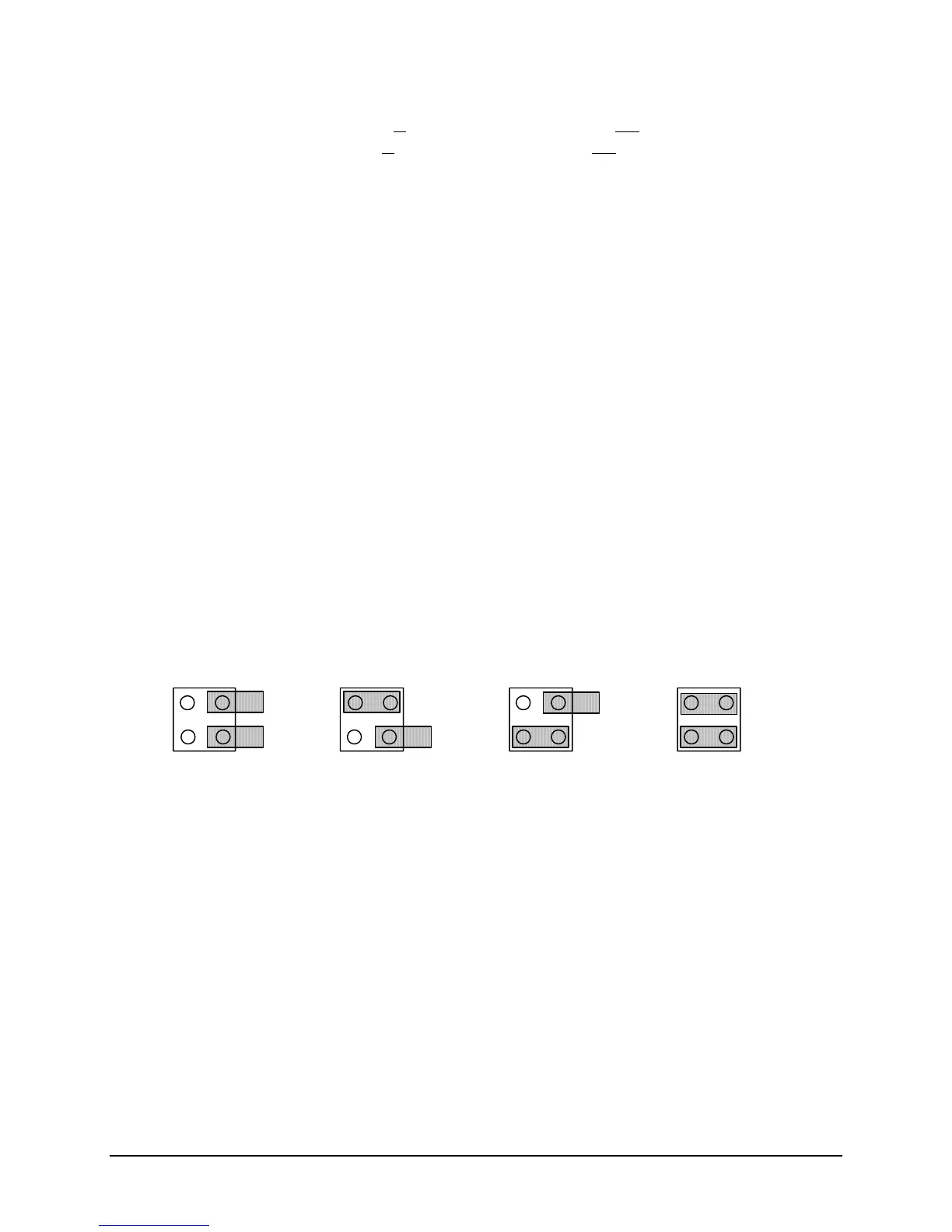
2.6.5 OSCILLATOR CONFIGURATION
The jumper blocks at J27 enable the processor (and the program) to determine which oscillator is
installed on the board. This provides for the selection of the specific gain and correction voltage
(i.e. the discipline voltage) for each oscillator. The jumpers are factory set for the oscillator in
your specific configuration, and shouldn’t need to be changed unless the oscillator type is
changed.
OCXO LPROTCXO
J27 OSCILLATOR CONFIGURATION
12
3
4
12
3
4
12
3
4
12
3
4
RB
For the TCXO, no jumpers are installed.
For the OCXO, jumper pins 1-2.
For the Rubidium LPRO, jumper pins 3-4.
For the Rubidium X-72, jumper pins 1-2, and 3-4.
2-8 ET6xxx ExacTime GPS TC & FG (Rev C) Symmetricom Inc
 Loading...