SYNRAD® 32-1 Operator’s Manual Version 2.2
32
Technical Reference
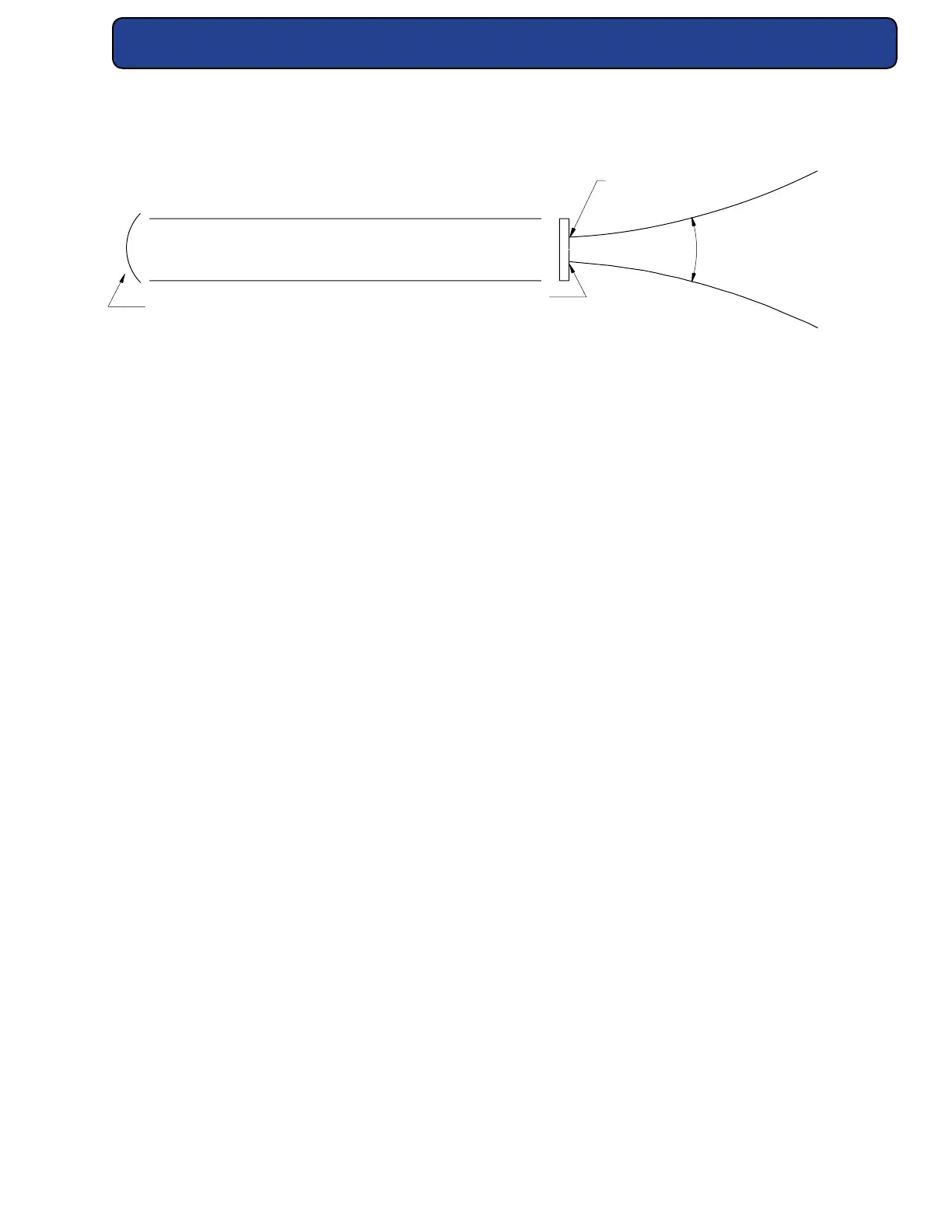
Ø
RF DISCHARGE REGION
TOTAL REFLECTOR
OUTPUT COUPLER
FULL ANGLE
BEAM WAIST DIA. 2.3 ± 0.5 mm
Figure 4-1 Beam characteristics.
Controlling Circuitry
Electrical description
Control of laser operation and power output levels is essentially performed using a single PCB.
The Control PCB connects the modulated signal to the RF amplier. It also provides electron-
ics to monitor performance of RF control, output circuitry, input power, temperature, PWM
accuracy, provides outputs to an externally accessible connector, and incorporates reverse
polarity protection.
Model 32-1 lasers use a single RF electrode requiring a single modulated RF drive input from
the Control PCB.
The modulated input PWM signal is generated externally to the laser and connected to the
input connector. This signal is connected to an optoisolator, the output of which is applied
to the PWM switch control circuit. The PWM switch control circuit gates the PWM switch o
and on at the frequency and duty cycle controlled by the modulation source. When the PWM
switch closes, a potential of +30 VDC is applied to the RF Driver. The PWM control circuit pro-
vides on/o gating of the PWM switch unless disabled by the ve-second delay, or the fault
shutdown circuits.
The ve-second delay disables PWM output to the RF amplier for a period of approximately
ve seconds after the Remote Keyswitch link is closed (power ON). Note that the supplied
DB-9 jumper plug can be removed to allow the user to insert a remotely located relay or
switch in series with the Remote Keyswitch.
Over temperature fault shutdown occurs when laser tube temperature reaches 60 °C ±2 °C.
Control board operation begins when the supply voltage rises above +18 VDC and remains
below +36 VDC. After start-up, the control board will shut the laser down if supply voltage
falls below +15 VDC or rises above +36 VDC.