SYNRAD® 32-1 Operator’s Manual Version 2.2
49
User I/O Connections
Technical Reference
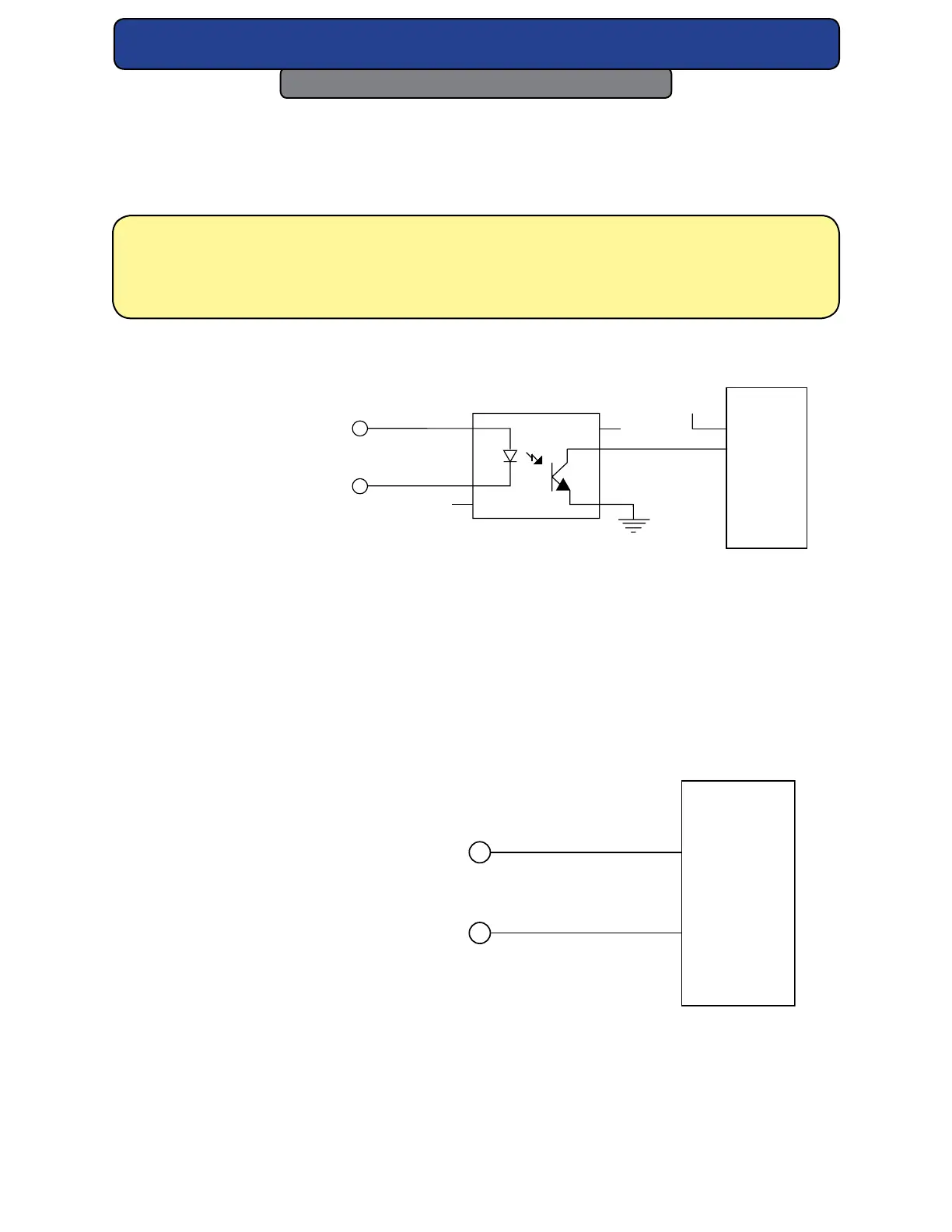
Sample output circuits
Figures below illustrate how to connect the laser’s Remote Ready LED Output to a Program-
mable Logic Controller (PLC) DC input module using current sourcing, current sinking, and
resistive pull-up methods.
4N29 OPTOISOLATOR
(9) REMOTE READY
LED OUTPUT
(2) SIGNAL GROUND
DB-9 CONNECTOR PINS
1
2
3
NC
NC
6
5
4
24 VDC GND
PLC
RTN
+24 VDC
INPUT
Figure 4-9 Remote Ready output to PLC input (PLC sourcing).
Note: You can use these same circuits to monitor the laser’s Remote Lase LED Output
(DB-9, Pin 8); however, the Remote Lase LED Output is not a steady state (on/o)
output. It is a Pulse Width Modulated (PWM) signal based on the PWM input signal
to the laser.
The following gure illustrates how to connect the Fault Shutdown Output signal to a PLC.
The Fault Shutdown Output function signals a laser shutdown due to an under/over voltage
condition, an over temperature condition, or failure of internal circuitry.
(1) FAULT SHUTDOWN
OUTPUT
(2) SIGNAL GROUND
DB-9 CONNECTOR PINS
RTN
INPUT
Figure 4-10 Fault Shutdown Output to PLC input.