SYNRAD® 32-1 Operator’s Manual Version 2.2
41
User I/O Connections
Technical Reference
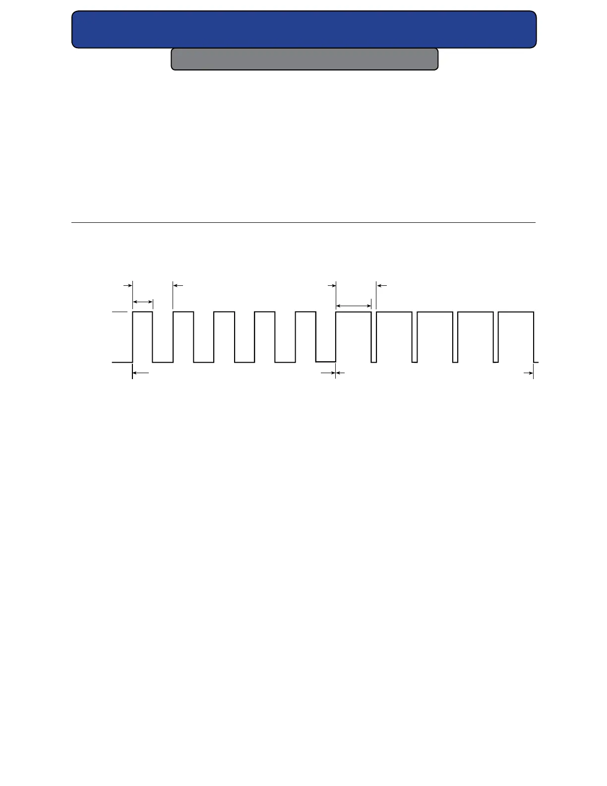
Table 4-5 PWM signal specications.
Laser State Minimum Nominal Maximum
Laser O Voltage 0.0 VDC 0.0 VDC +0.5 VDC
Laser On Voltage +3.5 V +5.0 VDC +10.0 VDC
Current (@ 5 VDC) — — — — 6 mA (32-1)
Frequency Range 0 Hz (DC) 5 kHz 20 kHz
Duty Cycle 0% — — 100%
5kHz PWM Signal at 50% Duty Cycle 5kHz PWM Signal at 95% Duty Cycle
100 µs
190 µs
200 µs
200 µs
0 VDC
5 VDC
Figure 4-6 PWM signal waveform.
Operating modes
External control
In addition to controlling your 32-1 laser using a UC-2000 Controller, controlling the laser
externally, without a UC-2000, is also possible. The two primary elements of laser control are
gating, the ability to turn the laser on and o at the appropriate times, and power, the ability
to control the laser’s output energy. Both gating and power can be handled by a device such
as a personal computer, Programmable Logic Controller (PLC), or a function generator capable
of sending PWM pulses at the proper time (gating) and with the proper duty cycle (power).
Analog voltage or analog current control
Although 32-1 lasers cannot be controlled directly by analog voltage or current signals, this
type of control is possible when using the UC-2000 Controller. The Controller is connected
normally to the laser and analog voltage or current signals sent to the UC-2000’s ANV/C con-
nector then control both gating and power.