SYNRAD® 32-1 Operator’s Manual Version 2.2
45
User I/O Connections
Technical Reference
User I/O connections
User I/O connection summary
Input/output signals
Sample I/O circuits
The PWM signal and all input/output (I/O) control signals are connected to the User I/O port.
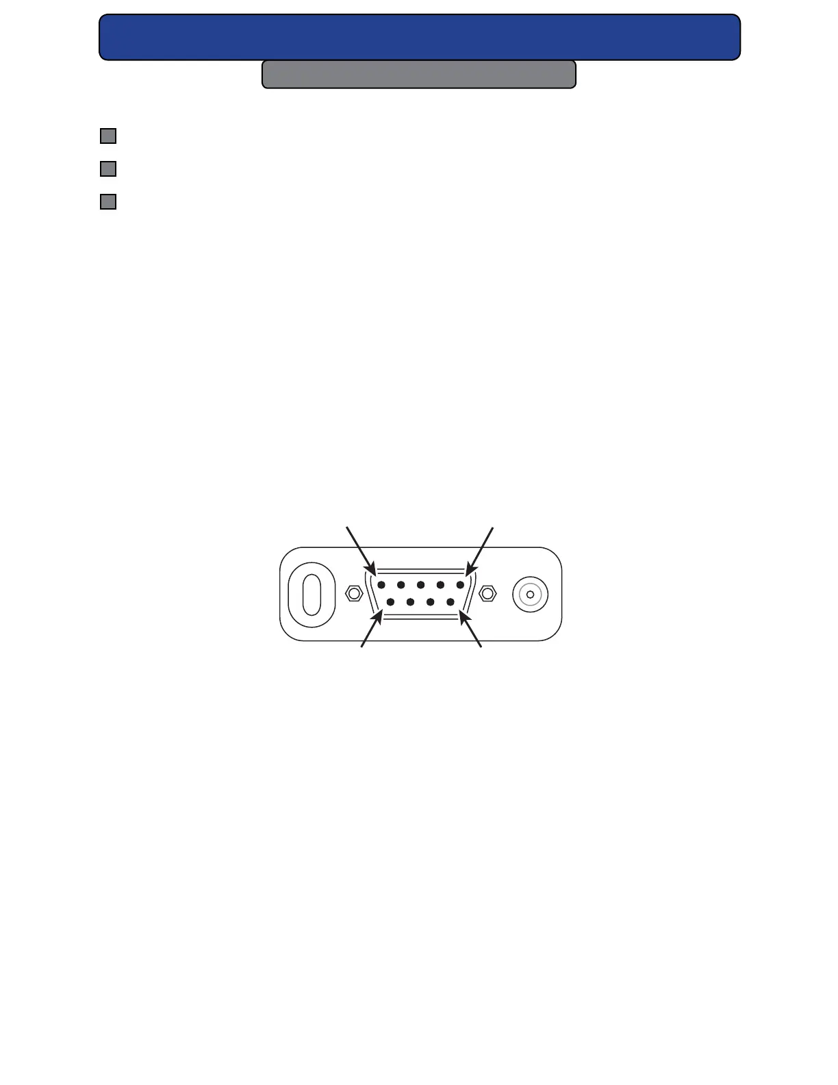
Please refer to the gure below for the 9 pin female D-type sub-miniature connector on the
side of the laser. The gure below illustrates the pin arrangement of the User I/O connector.
DB-9 connections
The gure below shows the physical layout and pin identication of the 32-1 DB-9 Connector.
Refer to the following tables in the next two pages describing input/output signal specica-
tions.
PIN 1
PIN 5
Figure 4-7 Physical layout of 32-1 DB-9 Connector.