D400-29-00 2 I56-580-03
Installation
NOTE: All wiring must conform to applicable installation
codes and regulations.
NOTE: Verify that all detector bases are installed, that the
initiating-device circuits have been tested, and that
the wiring is correct. (Refer to detector base
manual for testing procedure.)
WARNING
Disconnect the power from initiating-device circuits before
installing detectors.
1. Install Detectors:
a. Insert the detector into the detector base.
b. Turn the detector clockwise until the detector drops
into place.
c. Continue turning detector clockwise to lock it in
place.
2. After all detectors have been installed, apply power to
the control unit.
3. Test the detector using the magnet as described under
TESTING.
4. Reset the detector at the system control panel.
5. Notify the proper authorities that the system is in opera-
tion.
Tamper Resistance
The detector bases include a feature that, when activated,
prevents removal of the detector without the use of a tool.
Refer to the installation instruction manual of the detector
base to make use of this capability.
Testing
Before testing, notify the proper authorities that the heat
detector system is undergoing maintenance, and therefore
the system will temporarily be out of service. Disable the
zone or system undergoing maintenance to prevent un-
wanted alarms.
Detectors must be tested after installation and periodic
maintenance. The 5451 may be tested as follows:
A. Test Magnet (System Sensor Model No. M02-04)
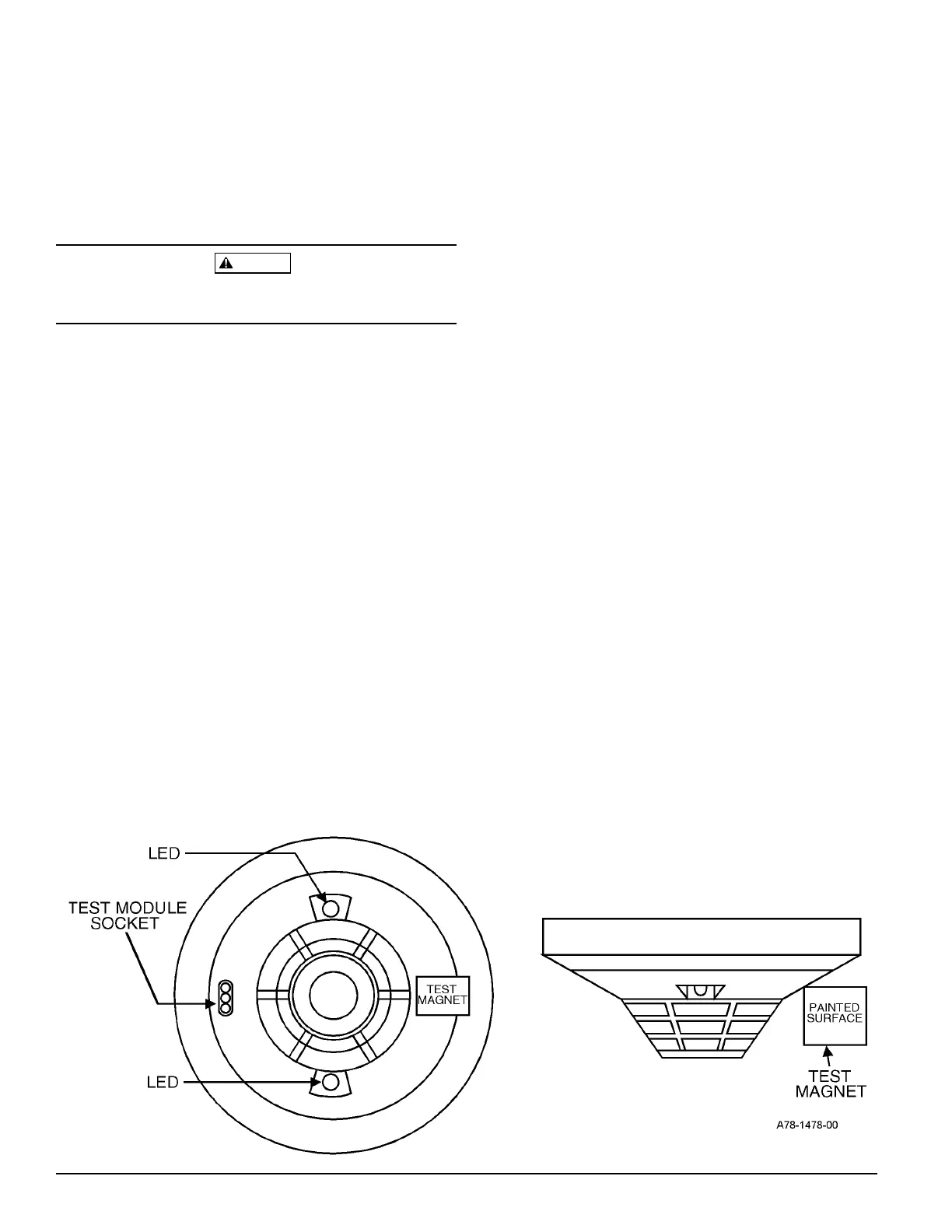
1. Position the magnet against the cover opposite the
test module socket. (See Figure 1.)
2. The LEDs on the detector should light within 10 sec-
onds. If the LEDs fail to light, check the power to the
detector and the wiring in the detector base.
3. Reset the detector at the system control panel.
Figure 1. Bottom and Side Views Showing Position of Test Magnet:
Technical Manuals Online! - http://www.tech-man.com