D450-03-00 1 I56-374-04
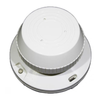
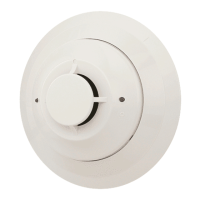
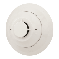
B402B Plug-in Detector Base
For use with the following smoke detectors:
1451, 2451, and 2451TH
INSTALLATION AND MAINTENANCE INSTRUCTIONS
A Division of Pittway
3825 Ohio Avenue, St. Charles, Illinois 60174
1-800-SENSOR2, FAX: 630-377-6495
Before Installing
Please read the System Sensor manual I56-407, Guide for
Proper Use of System Smoke Detectors, which provides de-
tailed information on detector spacing, placement, zoning,
wiring, and special applications. Copies of this manual are
available at no charge from System Sensor. (For installa-
tions in Canada, refer to CAN4-S524, Standard for the In-
stallation of Fire Alarm Systems, and CEC Part 1, Sec. 32.)
NOTICE: This manual should be left with the owner/user
of this equipment.
IMPORTANT: The detector used with this base must be
tested and maintained regularly following NFPA 72 require-
ments. The detector used with this base should be cleaned
at least once a year.
Specifications
Base Diameter: 6.2 inches (15.7 cm)
Base Height: 1.1 inches (2.8 cm)
Weight: 0.3 lb. (130 g)
Mounting: 4 inch square box with or without plaster ring. Min. Depth: 1.5 inches
4 inch octagon box. Min. Depth: 1.5 inches
3-1/2 inch octagon box. Min. Depth: 1.5 inches
Operating Temperature Range: 0° to +49°C (32° to 120°F)
Operating Humidity Range: 10% to 93 % Relative Humidity, Non-condensing
Electrical Ratings — includes base and detector
System Voltage: 24 VDC
Maximum Ripple Voltage: 4 Volts peak to peak
Start-up Capacitance: 0.02
µ
F Maximum
Standby Ratings: 20 VDC Minimum
29 VDC Maximum
120
µ
A Maximum
Alarm Ratings: 17 mA Minimum
36 mA Maximum
Reset Voltage: 1.4 VDC Minimum
Reset Time: 0.3 Seconds Maximum
(If used, the RA400 remote lamp operates within the specified
detector alarm currents.)
Start-up Time: 34.0 Seconds Maximum
Relay Contact Ratings
Resistive or Inductive (60% Power Factor):
Form A: 2.0A @ 30 VAC/DC
Form C: 2.0A @ 30 VAC/DC
0.6A @ 110 VDC
1.0A @ 125 VAC
General Description
The plug-in detector base B402B is used with System Sen-
sor model 2451 and 2451TH photoelectronic detector
heads, and model 1451 ionization detector head. The capa-
bility of plugging these detectors into a variety of special
bases makes them more versatile than equivalent direct-
wired models. Refer to the System Sensor catalog for other
available plug-in detector bases.
This B402B base is intended for use in 4-wire systems, with
screw terminals provided for power, remote annunciator,
and relay contact connections. These bases also contain a
resistor to provide current limiting in the alarm state.
Technical Manuals Online! - http://www.tech-man.com