D400-29-00 1 I56-580-03
INSTALLATION AND MAINTENANCE INSTRUCTIONS
A Division of Pittway
3825 Ohio Avenue, St. Charles, Illinois 60174
1-800-SENSOR2, FAX: 630-377-6495
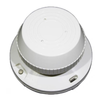
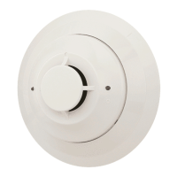
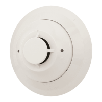
5451 Plug-in Rate-of-Rise
Thermal Detector with
Fixed Temperature Alarm
Specifications
Diameter: 4.1 inches (104 mm)
Height: 2.1 inches (53 mm)
Weight: 5 ounces (150 g)
Installation Temperatures: 32° to 100°F (0° to 38°C)
Operating Humidity Range: 10% to 93% Relative Humidity
Latching Alarm: Reset by momentary power interruption
Sensitivity 135°F (57°C) Fixed or 15°F/min rate-of-rise
Operating Voltage: 15-35 VDC
Standby Current: 100 µA
Before Installing
This detector must be installed in compliance with the
control panel installation manual and meet the require-
ments of the authority having jurisdiction. In addition, the
National Fire Protection Association has published codes,
standards, and recommended practices for the installation
and use of detectors, NFPA 72.
(For installation in Canada, refer to CAN/ULC-S524, Stan-
dard for the Installation of Fire Alarm Systems and CEC
Part 1, Sec. 32.)
Therefore, the installer must be familiar with these re-
quirements, with local codes, and any special require-
ments of the authority having jurisdiction.
NOTICE: This manual should be left with the owner/user
of this equipment.
IMPORTANT: This detector must be tested and main-
tained regularly following NFPA 72 requirements. The de-
tector should be cleaned at least once a year.
General Description
Model 5451 is a rate-of-rise with fixed temperature alarm
thermal detector utilizing a state-of-the-art dual thermistor
sensing circuit. These detectors are designed to provide
open area protection with 50-foot spacing capability, and
are to be used with compatible control panels only.
Two LEDs on each detector light to provide 360° visibility
of the detector indication. Remote LED annunciator capa-
bility is provided as standard, and the RA400Z remote LED
annunciator is available as an optional accessory.
Base Selection and Wiring Guide
Refer to the installation instructions for the plug-in detector
bases for base selection and wiring instructions. System
Sensor has available a variety of detector bases for these
heat detectors, including 2-wire applications with and
without relays and/or current limiting resistors for use with
control panels that require one. This detector is only to be
used with 400 and 400B series bases.
Install the System Sensor plug-in base to be used with the
detector following the instructions in the base manual.
Technical Manuals Online! - http://www.tech-man.com