D400-02-01 1 I56-277-08
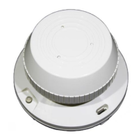
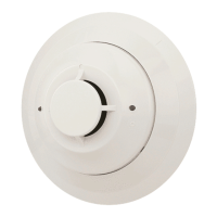
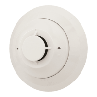
2451 and 2451TH Photoelectronic
Plug-in Smoke Detectors
INSTALLATION AND MAINTENANCE INSTRUCTIONS
A Division of Pittway
3825 Ohio Avenue, St. Charles, Illinois 60174
1-800-SENSOR2, FAX: 630-377-6495
Before Installing
Please thoroughly read the System Sensor publication, I56-
407, Applications Guide for System Smoke Detectors, which
provides detailed information on detector spacing, place-
ment, zoning, wiring, and special applications. Copies of
this guide are available at no charge from System Sensor.
(For installations in Canada, refer to CAN4-S524, Standard
for the Installation of Fire Alarm Systems and CEC Part 1,
Sec. 32.)
NOTICE: This manual should be left with the owner/user
of this equipment.
IMPORTANT: This sensor must be tested and maintained
regularly following NFPA 72 requirements. This sensor
should be cleaned at least once a year.
General Description
The 2451 photoelectronic detectors utilize state-of-the-art,
optical sensing chambers. These detectors are designed to
provide open area protection, and to be used with compat-
ible UL-listed control panels only. Model 2451TH has the
same specifications as Model 2451, with the addition of a
built-in fixed temperature (135°F - 57°C) thermal detection
unit. The capability of plugging these detectors into a vari-
ety of special bases makes them more versatile than
equivalent direct-wired models.
Specifications
Size
Height: 2.4 inches (61 cm)
Add 0.5 inches (13 cm) for thermal model 2451TH
Diameter: 4.0 inches (101 cm)
Weight: 0.5 lb. (277 g)
Operating Temperature Range: 0° to 49°C (32° to 120°F)
Operating Humidity Range: 10% to 93% Relative Humidity
Maximum Air Velocity: 3000 Ft./Min. (15 M/S)
Locking Alarm: Reset by momentary power interruption
Fixed Temperature Thermal: 135°F (57°C)
Two LEDs on each detector light to provide a local 360° vis-
ible alarm indication. They flash every ten seconds indicat-
ing that power is applied and the detector is operating
properly. The LEDs light continuously in alarm. Remote
LED annunciator capability is available as an optional ac-
cessory. These detectors also have the Latching Alarm fea-
ture. The alarm can be reset only by a momentary power
interruption. These detectors may be tested by activating
the internal reed switch with a magnet, or by inserting a
calibrated test card in a test slot after removing the detector
cover.
The 2451 has been approved for marine use in dry locations
by Underwriters Laboratory, Inc. The detector is to be used
in dry interior locations only.
Base Selection and Wiring Guide
Refer to the installation instructions for the Plug-in Detec-
tor Bases for base selection and wiring instructions. System
Sensor has a variety of detector bases available for this
smoke detector. This includes 2-wire applications with and
without relays and/or current limiting resistors, 4-wire and
120VAC applications. (Note: the 120VAC detector base is
not available in Canada.)
All bases are provided with screw terminals for power,
ground, remote annunciator connections and relay contact
connections, if applicable. The electrical ratings for each
detector-base combination are also included in the base
installation instructions.
Technical Manuals Online! - http://www.tech-man.com