D400-01-01 3 I56-278-05
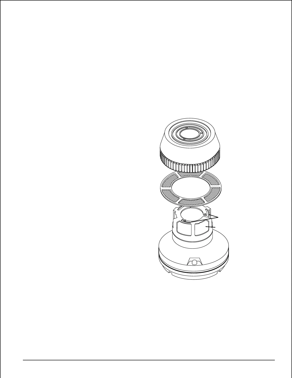
Figure 2:
LOCK PRONG
REMOVABLE SCREEN
(P/N RS14)
REMOVABLE
COVER
FOR
CLEANING
SENSING CHAMBER
A78-2340-00
B. Test Module (System Sensor Model No. MOD400R)
The MOD400 or MOD400R is used with a digital or ana-
log voltmeter to check the detector sensitivity as de-
scribed in the test module’s manual.
C. Aerosol Generator (Gemini 501)
Set the generator to represent 4%/ft. to 5%/ft. obscura-
tion as described in the Gemini 501 manual. Using the
bowl shaped applicator, apply aerosol until unit alarms.
Notify the proper authorities that the system is back on
line.
Detectors that fail these tests should be cleaned as de-
scribed under MAINTENANCE and retested. If the detec-
tors still fail these tests they should be returned for repair.
Maintenance
It is recommended that the detector be removed from its
mounting base to facilitate easier cleaning. The detector is
cleaned as follows:
NOTE: Before removing the detector, notify the proper au-
thorities that the smoke detector system is under-
going maintenance, and will temporarily be out of
service. Disable the zone or system undergoing
maintenance to prevent unwanted alarms.
1. Remove the detector screen and cover assembly by de-
pressing the three lock prongs on the top of the cover,
rotating the cover counterclockwise, and pulling the
screen and cover assembly away from the detector. (See
Figure 2.) Usage of a System Sensor CRT400 cover re-
moval tool is recommended.
2. Remove the screen from the cover.
3. Use a vacuum cleaner to remove dust from the screen,
the cover, and the sensing chamber.
4. After cleaning, snap the screen into the cover, then place
the cover and screen assembly on the detector, turning
clockwise until it is locked in place.
5. Reinstall the detector.
6. Test the detector as described under TESTING.
7. Notify the proper authorities that the system is back on
line.
Technical Manuals Online! - http://www.tech-man.com