D450-02-00 3 I56-352-05
Tamper-resist Feature
CAUTION
Do not use the tamper resist feature if the XR5 removal tool
is to be used.
This detector base also includes an optional tamper resist
feature that, when activated, prevents removal of the detec-
tor without the use of a tool.
To activate this feature, break the tab from the detector
base, as shown in Figure 3A, and install the detector. To re-
move the detector from the base once the tamper resist fea-
ture has been activated, insert a small-bladed screwdriver
into the slot in the side of the base and press the plastic le-
ver away from the detector head (see Figure 3B). This al-
lows the detector to be rotated counterclockwise and
removed.
PLASTIC LEVER
BREAK TAB AT
DOTTED LINE BY
TWISTING TOWARD
CENTER OF BASE.
USE SMALL-BLADED
SCREWDRIVER TO
PUSH PLASTIC LEVER
IN DIRECTION OF
ARROW.
A78-1175-03
Figure 3B. Removing detector head from base:Figure 3A. Activating tamperproof feature:
2-WIRE CONTROL PANEL
1
2
3
4
5
REMOTE
ANNUNCIATOR
1
2
3
4
5
REMOTE
ANNUNCIATOR
E
O
L
OPTIONAL FAULT TOLERANT WIRING
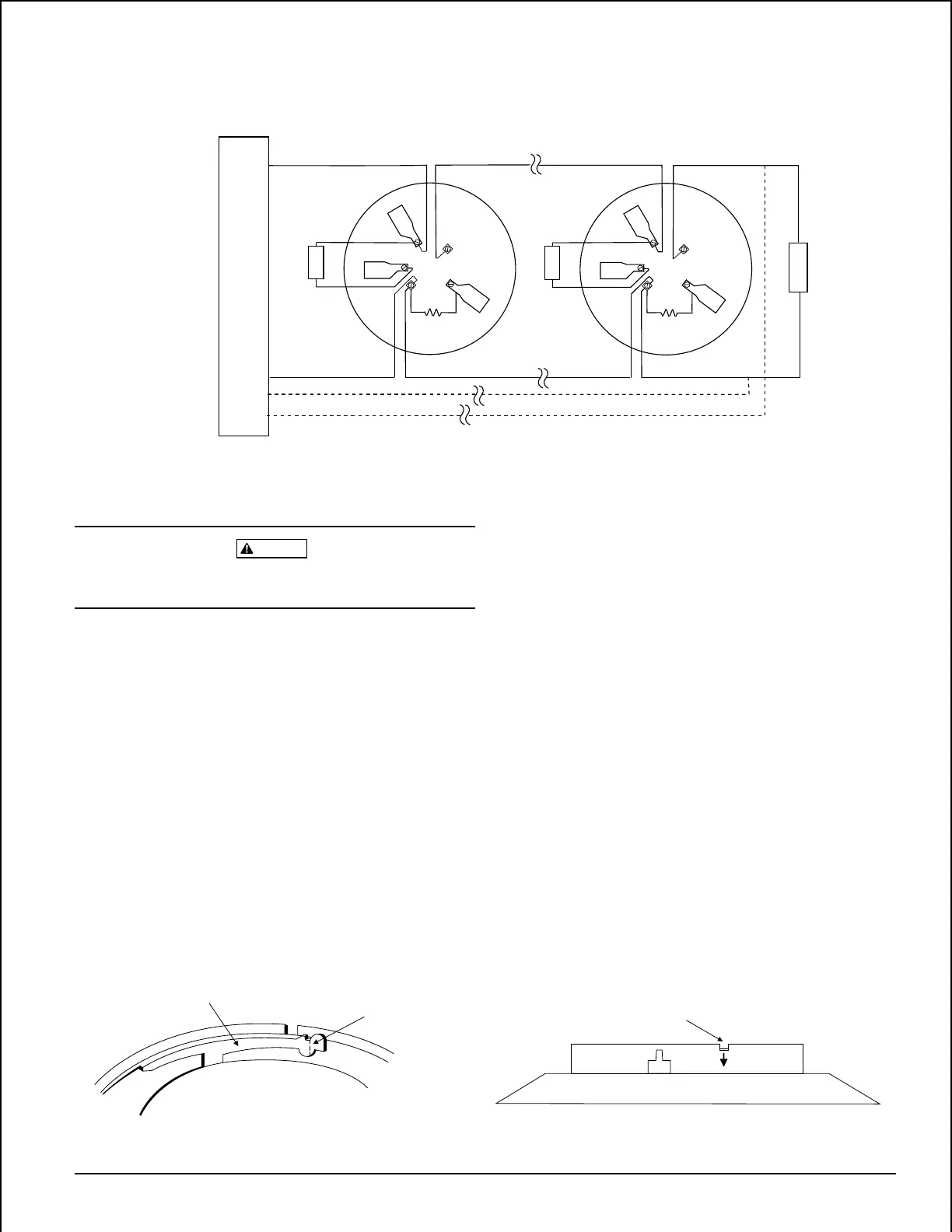
NOTE: For system supervision - Do not loop wire under
terminals 2, 3, and 5. Break wire run to ensure
system supervision of connections.
+
–
+
–
–
+
–
+
Figure 2. Typical wiring diagram for 2-wire detector systems:
A78-1175-10
Note: Head removal after the tamper resist feature has
been activated first requires removal of the decora-
tive ring.
The tamper resist feature can be defeated by breaking and
removing the plastic lever from the base. However, this per-
manently defeats the tamper resist feature.
Technical Manuals Online! - http://www.tech-man.com