D450-02-00 1 I56-352-05
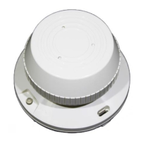
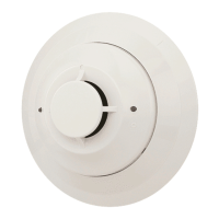
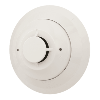
B401BR Plug-in Detector Base
INSTALLATION AND MAINTENANCE INSTRUCTIONS
A Division of Pittway
3825 Ohio Avenue, St. Charles, Illinois 60174
1-800-SENSOR2, FAX: 630-377-6495
Before Installing
Please thoroughly read the System Sensor manual I56-407,
Guide for Proper Use of System Smoke Detectors, which
provides detailed information on detector spacing,
placement, zoning, wiring, and special applications. Copies
of this manual are available at no charge from System
Sensor. (For installations in Canada, refer to CAN4-S524,
Standard for the Installation of Fire Alarm Systems, and
CEC Part 1, Sec. 32.)
NOTICE: This manual should be left with the owner/user
of this equipment.
IMPORTANT: The detector used with this base must be
tested and maintained regularly following NFPA 72 require-
ments. The detector used with this base should be cleaned
at least once a year.
Specifications
Base Diameter: 6.2 inches (157 mm) typical
Base Height: 1.1 inches (29 mm) typical
Weight: 0.3 lb. (130 g) typical
Mounting: 4 inch square box with or without plaster ring. Min. Depth: 1.5 inches
4 inch octagon box. Min. Depth: 1.5 inches
3-1/2 inch octagon box. Min. Depth: 1.5 inches
Operating Temperature Range: –10° to 60°C (14° to 140°F)
Note: Do not install where normal ambient temperature extends beyond 0° to 49°
(32° to 120°F)
Operating Humidity Range: 10% to 93% Relative Humidity
Electrical Ratings — includes base and detector
System Voltage: 24 VDC
Maximum Ripple Voltage: 4 Volts peak to peak
Start-up Capacitance: 0.02
µ
F Maximum
Standby Ratings: 17 VDC Minimum
32 VDC Maximum
120
µ
A Maximum
Alarm Ratings: 10 mA Minimum at 10.5 VDC
62 mA Maximum at 32 VDC
The optional RA400Z Remote Annunciator operates within the specified detector
alarm currents.
Reset Voltage: 2.50 VDC Minimum
Reset Time: 0.3 Sec Maximum
Start-up Time: 34.0 Sec Maximum
For use with the following detectors: 1451, 2451, and 2451TH
General Description
The plug-in detector base B401BR is used with System Sen-
sor 400 Series photoelectronic, ionization, and heat detec-
tor heads. The ability to accept a variety of detector heads
makes this base more versatile than equivalent direct-wired
models. Refer to the System Sensor catalog for other avail-
able plug-in detector bases.
This B401BR base is intended for use in 2-wire systems,
with screw terminals provided for power, ground, and re-
mote annunciator connections. The B401BR base also con-
tains a resistor to provide current limiting in the alarm
state.
Technical Manuals Online! - http://www.tech-man.com