D450-05-00 3 I56-376-06
Tamper-resistance Feature
CAUTION
Do not use the tamper-resistance feature if the XR5 removal
tool is to be used.
This detector base includes an optional tamper-resistance
feature that, when activated, prevents removal of the detec-
tor without the use of a tool.
To activate this feature, simply break off the tab on the de-
tector base shown in Figure 3A, then install the detector. To
remove the detector from the base once the tamper-resis-
tance feature has been activated, place a small-bladed
screwdriver into the small hole on the side of the base and
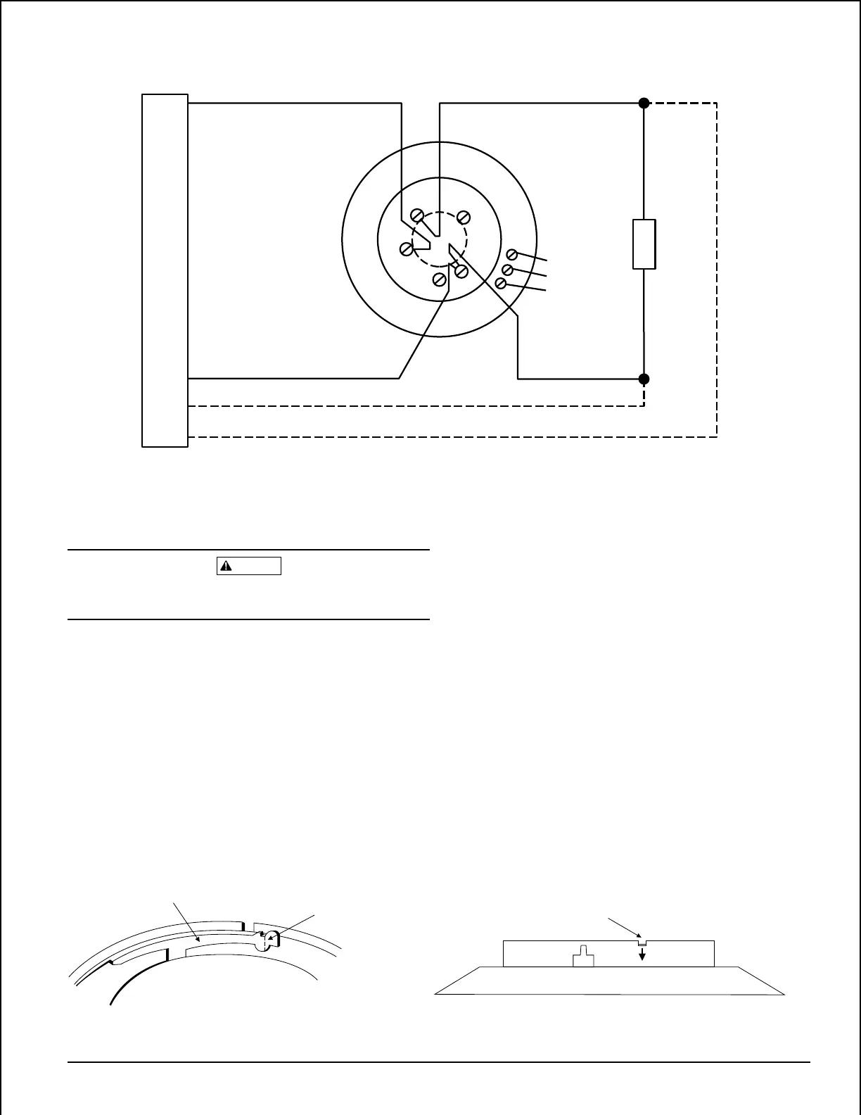
Figure 2. Typical wiring diagram:
A78-1577-00
(+) POWER LOOP
2-WIRE CONTROL PANEL
(–) POWER LOOP
3
2
4
5
1
12
13
14
COM CONTACT
N.C. AUXILIARY
N.O. FORM C
E
O
L
CLASS A OPTIONAL WIRING
push plastic lever away from the detector head (see Figure
3B). This will allow the detector to be rotated counterclock-
wise for removal.
NOTE: Head removal after the tamper-resistance feature
has been activated first requires removal of the
decorative ring.
The tamper-resistance feature may be defeated by breaking
and removing the plastic lever from the base, however this
prevents ever using the feature again.
Figure 3A. Activating tamper-resistance feature: Figure 3B. Removing detector head from base:
A78-1175-03
PLASTIC LEVER
BREAK TAB AT
DOTTED LINE BY
TWISTING TOWARD
CENTER OF BASE.
USE SMALL-BLADED
SCREWDRIVER TO
PUSH PLASTIC LEVER
IN DIRECTION OF
ARROW.
Technical Manuals Online! - http://www.tech-man.com