D400-50-00 1 I56-612-03
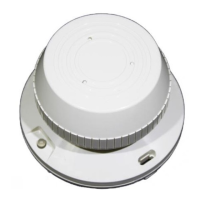
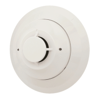
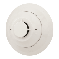
B401BH and B401BHA
Sounder Bases
INSTALLATION AND MAINTENANCE INSTRUCTIONS
A Division of Pittway
3825 Ohio Avenue, St. Charles, Illinois 60174
1-800-SENSOR2, FAX: 630-377-6495
Before Installing
Please thoroughly read the System Sensor manual I56-407,
Guide for Proper Use of System Smoke Detectors, which pro-
vides detailed information on detector spacing, placement,
zoning, wiring, and special applications. Copies of this
manual are available at no charge from System Sensor.
NFPA 72 and NEMA should be observed. (For installation
in Canada, refer to CAN/ULC-S524, Standard for the Instal-
lation of Fire Alarm Systems and CEC Part 1, Sec. 32.)
NOTICE: This manual should be left with the owner/user
of this equipment.
IMPORTANT: The detector used with these bases must be
tested and maintained regularly following NFPA 72 require-
ments. The detector used with these bases should be
cleaned at least once a year.
Specifications
Base Diameter: 6 inches (152 mm)
Base Height (less base and sensor): 0.75 inches (19mm)
Weight: 0.3 lb. (140 g)
Operating Temperature Range: 14
o
to 140
o
F (–10
o
to +60
o
C)
Operating Humidity Range: 10% to 95%, noncondensing
Electrical Ratings
Voltage: 17 to 32 VDC
Standby Current: 1.0 mA maximum
Alarm Current: 15 mA maximum
Maximum Ripple Voltage: 10% of supply voltage
Start-up Capacitance: 200 µF
Horn Input Current Requirement: 600 µA maximum
Sound Output: Greater than 90 dBa measured in anechoic room at 10 feet (3 meters), 24 volts.
85 dBa minimum measured in UL reverberant room.
General Description
Models B401BH and B401BHA sounder bases are intended
for use with System Sensor 400 Series plug-in sensor heads
in conventional 2-wire plug-in systems. Refer to systems
manuals for the maximum allowable number of units per
loop. The B401BH requires an external 24VDC (nominal)
supply with reverse polarity capability. The connections of
the external supply (terminals 1 and 2) and the initiating
loop (terminals 3, 4, and 5) are isolated in the B401BH to
prevent electrical interaction between them.
When the detector head’s visible LEDs are latched on for
approximately 10 seconds, the associated horn sounds. A
loop of horns can be made to sound by reversing the polar-
ity of the external supply.
NOTE: When the associated system is NOT used as a
supplementary evacuation system, the external
24VDC supply must be treated as a component of
the main power supply system with the result that
it falls under the requirements of NFPA 72.
Technical Manuals Online! - http://www.tech-man.com