Do you have a question about the System Sensor 1451 and is the answer not in the manual?
| Humidity Range | 10% to 93% RH non-condensing |
|---|---|
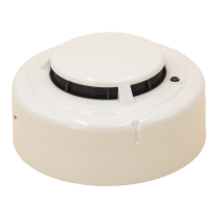
| Type | Photoelectric |
| Power Source | 24 VDC |
| Temperature Range | 32°F – 120°F (0°C – 49°C) |
| Height (including base) | 2.0 inches (51 mm) |
| Compatibility | Compatible with control panels |
Details size, weight, operating conditions, and latching alarm feature.
Guidance on prerequisite manuals and important notices before installation.
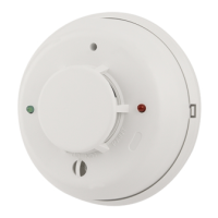
Overview of the detector's dual chamber ionization technology and features.
Step-by-step instructions for installing the detector into its base.
Procedures for testing the detector's functionality using various methods.
Instructions on how to clean and maintain the smoke detector.
Discusses inherent limitations and applications of smoke detectors.
Details the warranty terms and conditions for the smoke detector.
Outlines physical, operating, and electrical specifications for photoelectronic detectors.
Prerequisites and guidance before starting installation of photoelectronic detectors.
Explains the optical sensing chambers and features of photoelectronic detectors.
Step-by-step guide for installing the 2451/2451TH detectors into their bases.
Methods to test the photoelectronic detectors' sensitivity and alarm functions.
Procedures for cleaning and maintaining the photoelectronic smoke detectors.
Covers limitations and specific applications for heat detectors.
Details the warranty coverage for the heat detector products.
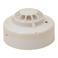
Lists thermal detector specifications including temperature, voltage, and current.
Installation prerequisites and compliance information for thermal detectors.
Describes the dual thermistor sensing circuit and features of thermal detectors.
Instructions for installing the 4451HT/4451HTA thermal detector heads.
Procedures for testing thermal detector sensitivity using heat or magnets.
Guidance on cleaning and maintaining the thermal detectors for optimal performance.
Details the limitations and specific use cases for heat detection devices.
Details specifications for the rate-of-rise and fixed temperature thermal detector.
Pre-installation requirements and compliance information for the 5451 detector.
Overview of the 5451 detector's dual thermistor circuit and features.
Instructions for installing the 5451 rate-of-rise and fixed temperature detector.
Explains the tamper-resistant feature for securing the detector head.
Methods for testing the 5451 detector's response to heat and magnets.
Guidance on cleaning and maintaining the 5451 thermal detector.
Discusses the limitations and specific applications for heat detection devices.
Lists base specifications including dimensions, voltage, and current ratings.
Prerequisites and guidance for installing the B401B detector base.
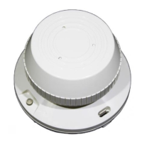
Overview of the B401B base for 2-wire systems and compatible detectors.
Instructions for mounting the detector base to junction boxes.
Guidelines for proper wiring and installation of detector bases.
Detailed steps for connecting wires to the detector base terminals.
Explains how to activate and use the tamper-resistant feature on the base.
Covers limitations and general applications of smoke detection technology.
Details the specifications for the B401BR detector base, including electrical ratings.
Pre-installation guidance for the B401BR plug-in detector base.
Describes the B401BR base's compatibility and use in 2-wire systems.
Instructions for physically mounting the B401BR detector base.
General guidelines for wiring and installing detector bases correctly.
Steps for making electrical connections to the B401BR base terminals.
Information on activating and using the tamper-resistant feature of the base.
Details about optional remote annunciator units compatible with the base.
Discusses the limitations and proper use of smoke detection technology.
Lists the technical specifications for the B401 plug-in detector base.
Pre-installation checks and guidance for the B401 detector base.
Overview of the B401 base's versatility and intended use with various detectors.
Instructions for securely mounting the B401 detector base.
Best practices for wiring and installation of detector bases.
Procedure for making electrical connections to the B401 base.
Details on activating and using the tamper-resistant feature of the base.
Information on compatible optional remote annunciator units.
Covers the limitations and proper application of smoke detection technology.
Details the electrical and physical specifications for the B402B detector base.
Pre-installation guidance and compliance for the B402B base.
Overview of the B402B base's intended use in 4-wire systems.
Instructions for mounting the B402B detector base to electrical boxes.
Best practices for wiring and installation of detector bases.
Steps for making electrical connections to the B402B base.
Explanation of the tamper-resistant feature for securing the base.
Covers the limitations and proper application of smoke detection technology.
Lists the specifications for the B404B plug-in detector base, including relay contacts.
Pre-installation guidance for the B404B detector base and its associated manuals.
Overview of the B404B base's design for 4-wire systems with relay connections.
Description of the terminal functions for the B404B detector base.
Instructions for mounting the B404B detector base to junction boxes.
Guidelines for proper wiring and installation of detector bases.
Steps for making electrical connections to the B404B base, including 120VAC systems.
Explains the tamper-resistant feature for securing the B404B detector base.
Discusses the limitations and proper use of smoke detection technology.
Details specifications for the B406B plug-in base, including operating temperature range.
Pre-installation guidance and compatibility checks for the B406B base.
Overview of the B406B base's use with conventional detector heads in 2-wire systems.
Instructions for mounting the B406B detector base to electrical boxes.
Guidelines for proper wiring and installation of detector bases.
Steps for making electrical connections to the B406B base terminals.
Covers the limitations and proper application of smoke detection technology.
Lists the specifications for the B401R plug-in detector base, including voltage and current ratings.
Pre-installation guidance for the B401R detector base and its associated manuals.
Overview of the B401R base's design for 2-wire systems and remote annunciator connections.
Description of the terminal functions for the B401R detector base.
Instructions for mounting the B401R detector base to junction boxes.
Guidelines for proper wiring and installation of detector bases.
Details on activating and using the tamper-resistant feature of the base.
Information on compatible optional remote annunciator units.
Covers the limitations and proper application of smoke detection technology.
Details specifications for sounder bases, including sound output and electrical ratings.
Pre-installation guidance for sounder bases and compatibility with smoke detectors.
Overview of sounder bases used with 2-wire systems and their horn functionality.
Description of terminal functions for the sounder bases.
Guidelines for proper wiring and installation of sounder bases.
Procedures for testing the sounder bases and associated detector heads.
Discusses the limitations and proper application of smoke detection technology.
Details specifications for the B401BR750 detector base, including voltage and current ratings.
Pre-installation guidance for the B401BR750 plug-in detector base.
Overview of the B401BR750 base's design for 2-wire systems and current limiting.
Instructions for mounting the B401BR750 detector base to electrical boxes.
Guidelines for proper wiring and installation of detector bases.
Steps for making electrical connections to the B401BR750 base terminals.
Details on activating and using the tamper-resistant feature of the base.
Covers the limitations and proper application of smoke detection technology.