D400-02-01 3 I56-277-08
Testing
Before testing, notify the proper authorities that the smoke
detector system is undergoing maintenance and will tem-
porarily be out of service. Disable the zone or system un-
dergoing maintenance to prevent unwanted alarms.
Detectors must be tested after installation and periodic
maintenance. To test the 2451:
NOTE: Before testing the detector, check to ensure that the
LEDs are blinking. If they are not, the detector has
lost power (check the wiring) or it is defective (re-
turn for repair).
A. Test Magnet (System Sensor model no. M02-04-00)
1. Place the magnet against the cover opposite the test
module slot to activate the test feature (see Figure 1).
2. The LEDs should latch on within 5 seconds indicating
alarm and annunciating the panel.
B. Calibrated Test Card (System Sensor no. R59-18-00)
1. Remove the detector cover by placing a small bladed
screwdriver in the side slot of the detector cover,
twisting it slightly until the cover can be turned coun-
terclockwise for removal.
2. Insert the NO ALARM end of the test card fully into
the test slot (see Figure 2) then slide it counterclock-
wise until it stops.
3. Wait for at least 20 seconds. The detector should NOT
alarm.
4. Remove the test card by sliding it clockwise before re-
moving, then insert the ALARM end.
5. The LEDs should latch on within 20 seconds indicat-
ing alarm and annunciating the panel.
6. Put the cover back by gently rotating it clockwise un-
til it locks in place.
C. Test Module (System Sensor no. MOD400R)
The MOD400R is used with your DMM or voltmeter to
check the detector sensitivity as described in the
MOD400R’s manual.
D. Aerosol Generator (Gemini 501)
Set the generator to represent 4% to 5%/Ft. obscuration
as described in the Gemini 501 Manual. Using the bowl
shaped applicator, apply aerosol until the unit alarms.
E. Direct Heat Test (2451TH only)
To test the bi-metallic thermal collector, aim a heat
source, such as a low powered heat gun or blow dryer,
across the detector. Hold the heat source about 12 inches
(30 cm) from the detector to avoid damaging the plastic.
When the temperature rises to greater than 135°F
(57°C), the detector should latch into the alarm. The bi-
metallic collector automatically resets after the test.
Notify the proper authorities that the detection system is
back on line.
Detectors that fail these tests should be cleaned as de-
scribed under MAINTENANCE and retested. If the detec-
tors still fail these tests they should be returned for repair.
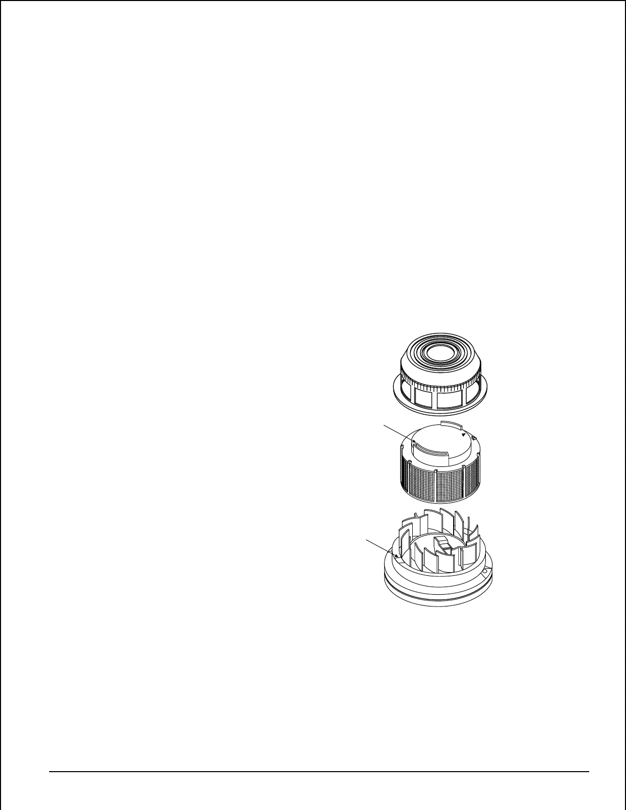
Figure 2:
REMOVABLE HEAD COVER
CLEANABLE SCREEN
HEAD COVER
REMOVAL SLOT
VANED CHAMBER
TEST SLOT
P/N RS24 (W/O THERMAL)
A78-1213-01
Technical Manuals Online! - http://www.tech-man.com