D450-08-00 3 I56-338-07
The zone wiring of the detector bases should be checked
before the detector heads are installed. To make this
possible, this base contains a special spring-type shorting
jumper (shown in Figure 1). After a detector base is
properly wired and mounted to an electrical box, make
sure that the shorting spring is in contact with terminal 3.
This temporary connection permits the wiring of the loop
to be checked for continuity before installation of the
detector heads. The shorting spring in the base
automatically disengages when the detector head is
removed from the base. DO NOT remove the shorting
spring since it reengages as the detector head is turned in
the base, completing the circuit.
Tamper-resistance Feature
This detector includes an optional tamper-resistance fea-
ture that prevents its removal from the base without the
use of a tool.
NOTE: DO NOT use the tamper-resistant feature if the XR-
5 removal tool is to be used.
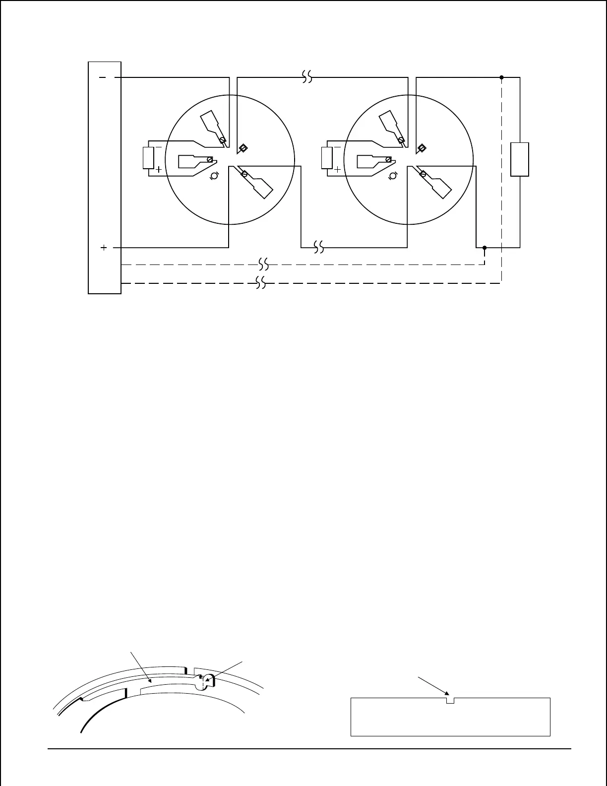
Figure 2. Typical 2-wire detector wiring configuration:
A78-1175-04
5
2
3
4
1
REMOTE
ANNUNCIATOR
5
2
3
4
1
REMOTE
ANNUNCIATOR
2-WIRE CONTROL PANEL
E
O
L
CLASS A OPTIONAL WIRING
To make the detector tamper-resistant, remove the smaller
tab by breaking it at the scribed line on the tamper-resistant
tab before installing the detector (see Figure 3A). The
tamper-resistant tab is on the detector mounting base.
To remove a tamper-resistant detector from the base, use a
pocket screwdriver, or similar tool, to depress the tamper-
resistant tab and turn the detector counterclockwise. The
tab is accessible through the slot on the mounting base (see
Figure 3B).
The tamper-resistance feature can be defeated by breaking
and removing the plastic lever from the base. However, this
permanently disables the tamper-resistance feature.
Optional Remote Annunciator Units
The model RA400Z remote LED annunciator is available as
an optional accessory. This unit has a rectangular plate that
fits U.S. single-gang light switch boxes. If a different type of
remote annunciator is used, it must be rated for the appro-
priate voltage, which is 2.75 to 3.0V.
PLASTIC LEVER
BREAK TAB AT
DOTTED LINE BY
TWISTING TOWARD
CENTER OF BASE.
USE SMALL-BLADED
SCREWDRIVER TO
PUSH PLASTIC LEVER
IN DIRECTION OF
ARROW.
A78-1468-02
Figure 3A. Activating tamper-resistance feature: Figure 3B. Removing detector head from base:
Technical Manuals Online! - http://www.tech-man.com