D450-04-00 2 I56-375-03
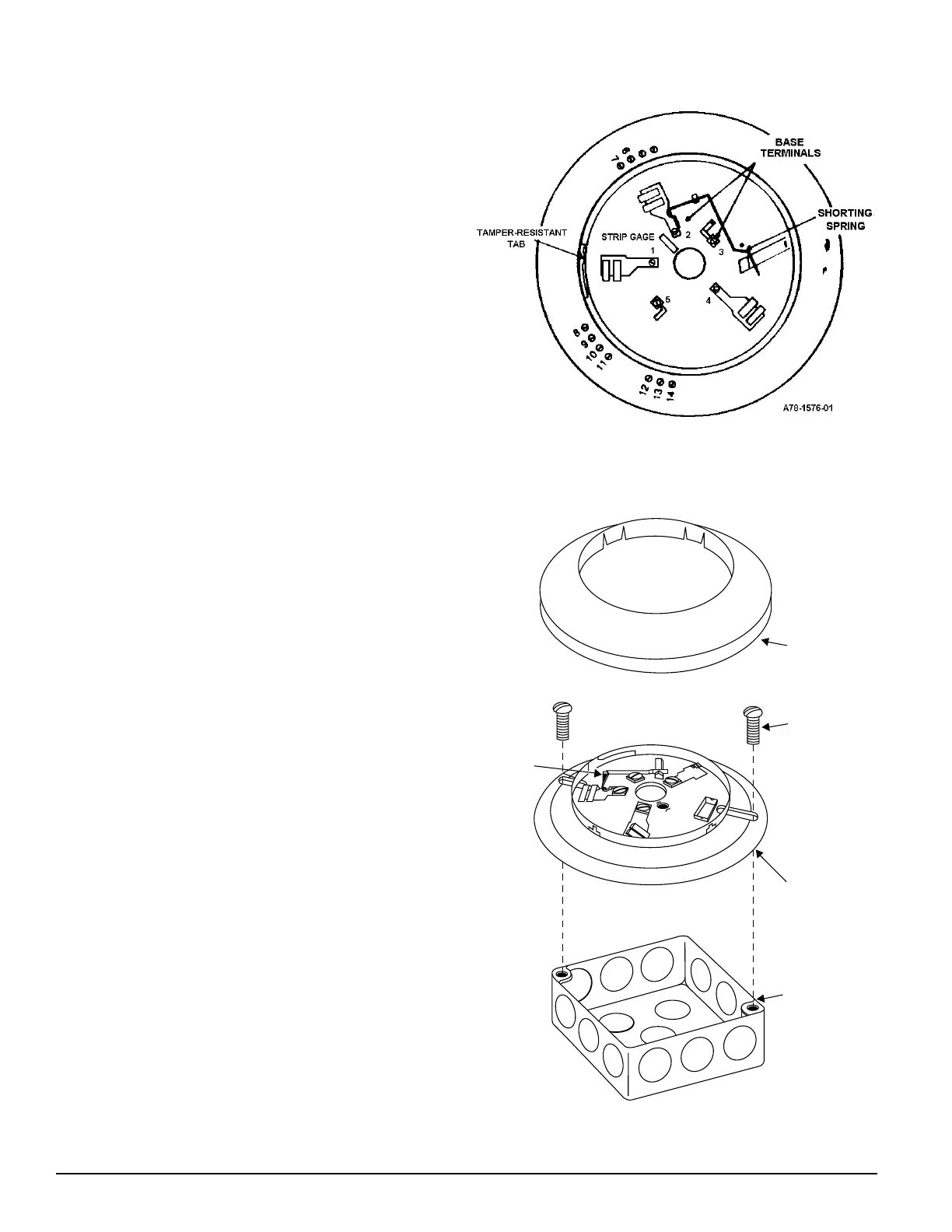
Base Terminals
No. Function
1 Remote Annunciator (+)
2 Test Coil (+)
3 Not used
4 Remote Annunciator (–)
5 RTC (–)
6 N.O. Supervisory Relay
7 N.O Form A Contacts
8 N.O. Alarm Relay
9 N.O. Form A
10 C. Initiation
11 C. Contacts
12 N.O. Alarm Relay
13 N.C. Form C
14 C. Auxiliary Contacts
Mounting
The detector base mounts directly to 3-1/2 inch and 4-inch
octagon boxes and 4-inch square boxes, with or without
plaster rings. To mount the base, remove the decorative
ring by rotating it in either direction to unhook the snaps
before separating the ring from the base. Use the screws
supplied with the junction box to attach the base to the box
through the appropriate mounting slots in the base.
Position the decorative ring around the base and rotate it in
either direction until the ring snaps into place (please see
Figure 2).
Installation Guidelines
All wiring must be installed in compliance with the Na-
tional Electrical Code, all applicable local codes, and any
special requirements of the authority having jurisdiction,
using the proper wire size. The conductors used to connect
smoke detectors to control panels and accessory devices
should be color-coded to reduce the likelihood of wiring er-
rors. Improper connections can prevent a system from re-
sponding properly in the event of a fire.
For signal wiring (the wiring between interconnected de-
tectors), it is recommended that the wire be no smaller
than 16 gauge (1.5 square mm), and that two- or three-con-
ductor wire be no smaller than 18 gauge (1.0 square mm).
For best performance, alarm loop conductors should be in-
stalled in separate grounded conduit or shielded cable to
protect the alarm loop from extraneous electrical interfer-
ence.
Smoke detectors and alarm systems control panels have
specifications for allowable loop resistance. Consult the
control panel manufacturer’s specifications for the total
loop resistance allowed for the particular model control
panel being used before wiring the detector loops.
}
}
}
A78-1175-01
Figure 2. Mounting base to box:
SNAP ON
DECORATIVE
RING
SCREWS (NOT
SUPPLIED)
DETECTOR
BASE
BOX (NOT
SUPPLIED)
SHORTING
SPRING
Figure 1. Base terminals:
Technical Manuals Online! - http://www.tech-man.com