3 I56-351-03
This temporary connection permits the wiring of the loop
to be checked for continuity before installation of the
detector heads.
The shorting spring in the base will automatically
disengage when the detector head is removed from the
base. DO NOT remove the shorting spring, since it
reengages as the detector head is turned into the base,
completing the circuit.
Once all the detector bases have been wired and mounted,
and the loop wiring has been checked, the detector heads
may be installed in the bases.
Tamper-resistance Feature
This detector base also includes an optional tamper-resis-
tance feature that, when activated, prevents removal of the
detector without the use of a tool.
CAUTION
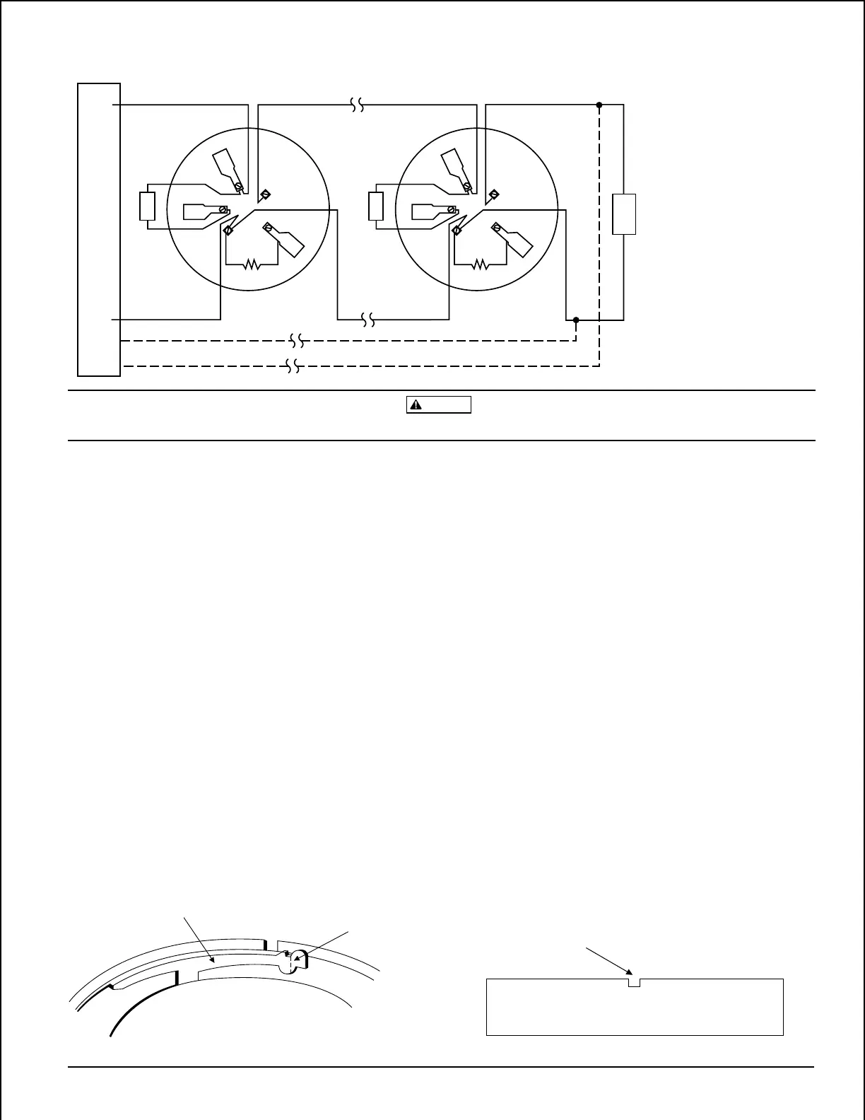
Do not loop wire under terminals. Break wire run to provide supervision of connections.
REMOTE
ANNUNCIATOR
2
1
3
5
4
+
–
2-WIRE CONTROL PANEL
+
–
REMOTE
ANNUNCIATOR
2
1
3
5
4
+
–
E
O
L
CLASS A OPTIONAL WIRING
NOTE: IF REMOTE ANNUNCIATOR
IS NOT USED, POLARITY TO
THESE TERMINALS MAY BE
REVERSED.
A78-1175-05
Figure 3. Typical wiring diagram for 2-wire detector system:
PLASTIC LEVER
BREAK TAB AT
DOTTED LINE BY
TWISTING TOWARD
CENTER OF BASE.
Figure 4. Activating tamper-resistance feature: Figure 5. Removing detector head from base:
A78-1468-02
USE SMALL-BLADED
SCREWDRIVER TO
PUSH PLASTIC LEVER
IN DIRECTION OF
ARROW.
To activate this feature, break off the tab on the detector
base (see Figure 4), then install the detector. To remove the
detector from the base after the tamper-resistance feature
has been activated, place a small standard screwdriver into
the small hole on the side of the base, and push the plastic
lever away from the detector head (see Figure 5). This will
allow the detector to be rotated counterclockwise for
removal.
The tamper-resistance feature may be defeated by breaking
and removing the plastic lever from the base, however this
prevents ever using the feature again.
Optional Remote Annunciator Units
The model RA400Z Remote Annunciator LED is available
as an optional accessory. This unit has a rectangular plate
that fits U.S. single-gang light switch boxes. If a different
type of remote annunciator is used, it must use less than
5ma at 3.0 V.
Technical Manuals Online! - http://www.tech-man.com