D400-50-00 2 I56-612-03
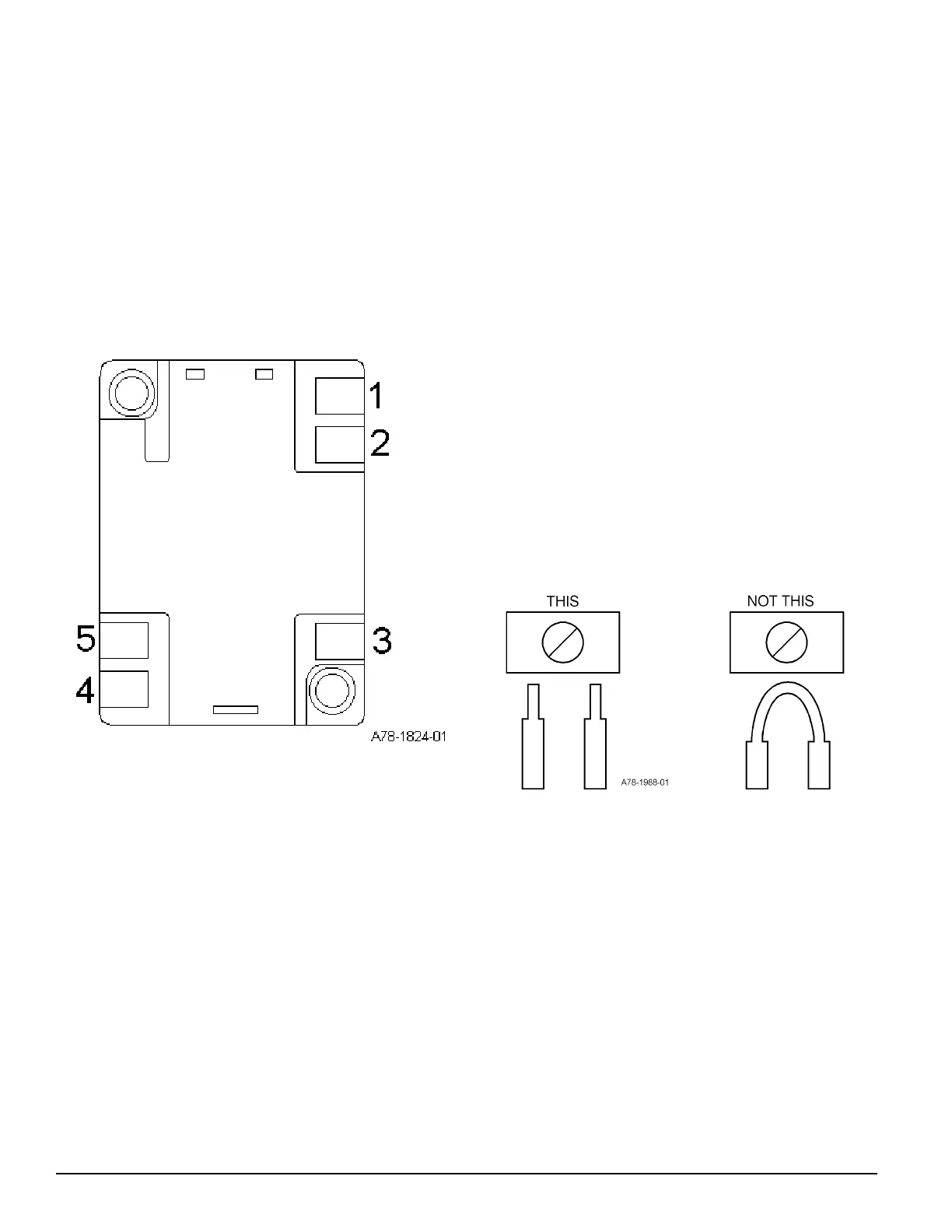
B401BH and B401BHA Terminals
No. Function
1 External Supply Positive (+)
2 External Supply Negative (–)
3 Negative (–) V in
4 Positive (+) V In and V Out
5 Negative (–) V Out
Terminals 3, 4, and 5 are used for the communication/initi-
ating circuit.
Installation Wiring Guidelines
All wiring must be installed in compliance with the Na-
tional Electrical Code and all applicable local codes and
any special requirements of the authority having jurisdic-
tion, using the proper wire size. The conductors used to
connect smoke detectors to control panels and accessory
devices should be color-coded to reduce the likelihood of
wiring errors. Improper connections can prevent a system
from responding properly in the event of a fire.
For signal wiring (the wiring between interconnected de-
tectors), it is recommended that the wire be no smaller
than AWG 18. However, the screws and clamping plate in
the base can accommodate wire sizes up to AWG 12. The
use of twisted pair wiring or shielded cable for the power
(+ and –) loop is recommended to minimize the effects of
electrical interference on the initiating loop.
Begin electrical connections by stripping about 3/8" insula-
tion from the end of the wire. Then, slide the bare end of
thewire under the clamping plate and tighten the clamping
plate screw. Break the wire at each terminal to ensure that
the connections are supervised, as shown in Figure 2.
Figure 2.
DO NOT loop the wire under the clamping plate.
Check the zone wiring of the detector base before the de-
tector heads are installed. Perform continuity, base polarity,
and dielectric tests on the wiring.
Smoke detectors and alarm system control panels have
specifications for allowable supervision current. Consult
the control panel manufacturer’s specifications for the total
loop current supervision allowed for the control panel be-
ing used before wiring the detector loops.
Figure 1. Terminal Layout:
Technical Manuals Online! - http://www.tech-man.com