D400-50-00 3 I56-612-03
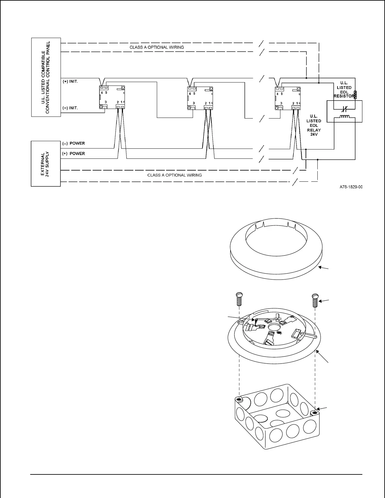
Figure 3. Typical wiring layout:
SNAP ON
DECORATIVE
RING
SCREWS (NOT
SUPPLIED)
DETECTOR
BASE
BOX (NOT
SUPPLIED)
SHORTING
SPRING
Wiring Instructions
The shorting spring in the base will disengage automati-
cally when the detector head is removed from the base.
DO NOT remove the shorting spring since it reengages as
the detector head is turned into the base, completing the
circuit.
A typical wiring for a two-wire conventional system is
shown in Figure 3. Refer to this diagram as needed while
wiring the base into the system.
NOTE: Figure 3 shows external 24V supply polarity when
the loop system is in standby (NOT alarming).
Mounting
NOTE: It is recommended that the base be completely
wired before mounting.
See Figure 4. Attach the base directly to an electrical box
using the screws supplied with the box. Then, use the plas-
tic screw covers, supplied with the base, to cover the
screws.
The sounder base is 1.1 inches (28 mm) deep. Electrical
boxes must be 4 inches (102 mm) square by at least 1-1/2
inches (38 mm) deep; 2-1/8 inches (54 mm) is recom-
mended.
Figure 4. Mounting to an electrical box:
A78-1175-01
Technical Manuals Online! - http://www.tech-man.com